1
\$\begingroup\$

I am building a circuit that uses a rechargeable battery and also has a USB port so it can be plugged in to charge the battery and power the system.

I am using a buck/boost converter to supply 3.3V for the circuit. I want the input for the converter to be the battery voltage when not connected to USB, but when plugged in, I want the input to be the USB.

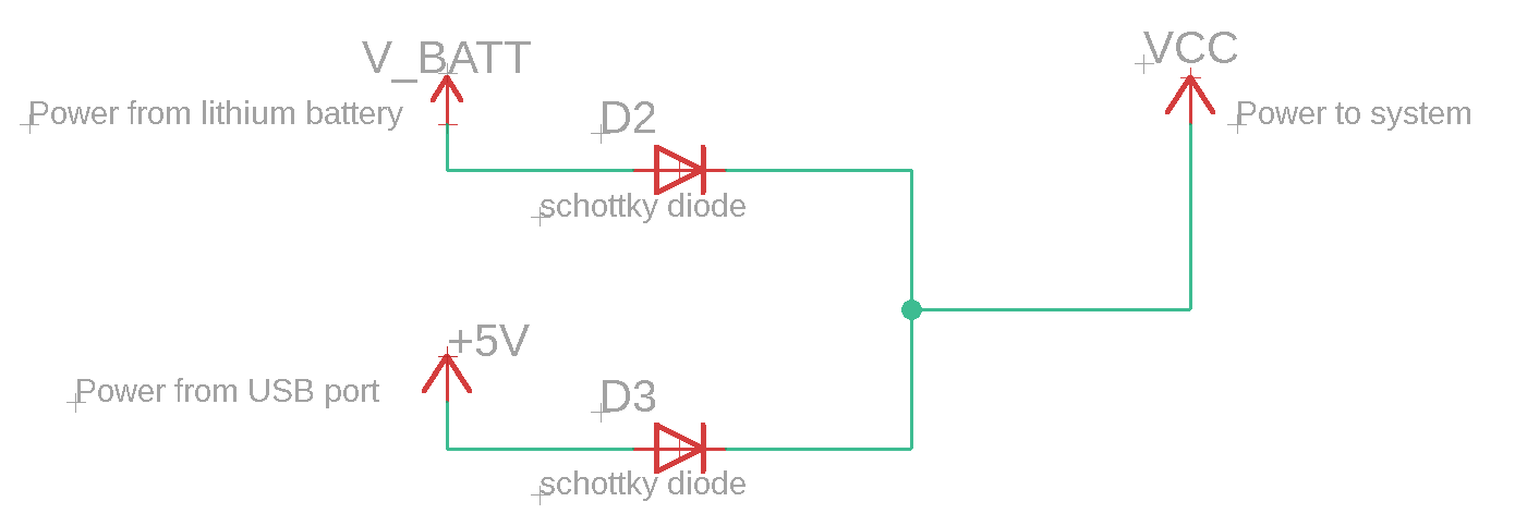
One way I thought to do this was with a low forward voltage drop diode in series with each supply. Think it would work, but still some voltage drop, not the most efficient.

Using Diodes

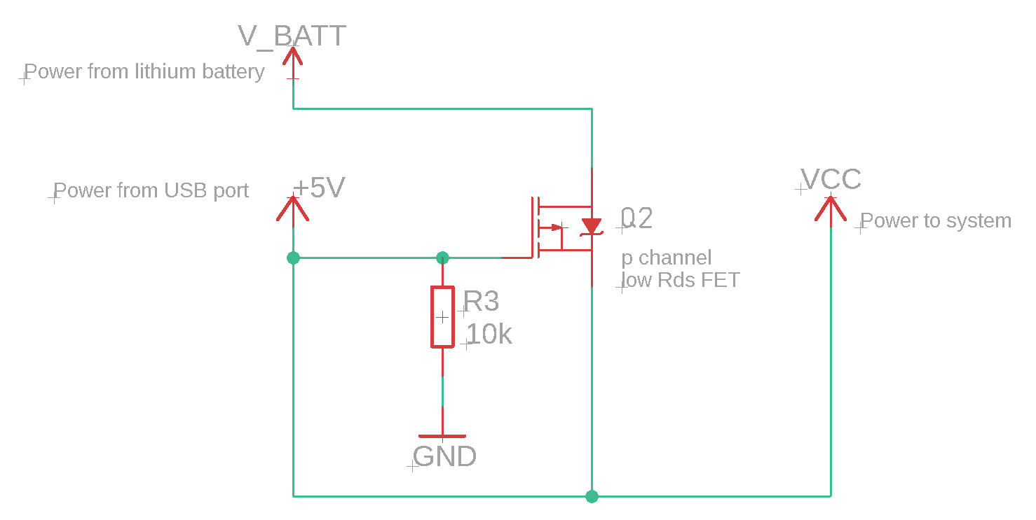
Another way I thought would be with a P channel FET that switches the battery voltage off when USB 5V is at the gate. Seems like the better method.

Using P Channel MOSFET

Would either of these solutions work? Thanks

EDIT

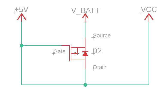
Following the advice given, this solution seems like it should work: *Note the symbol for P channel Fet was re drawn from original image so that source is on top and drain on bottom

enter image description here

\$\endgroup\$
1
  • \$\begingroup\$ Do you understand that your 3rd circuit has several fatal flaws? 1) Gate is tied to Drain. 2) The body diode of the FET feeds any voltage that is Vbatt + 1 diode drop right into the battery. This is NOT good. \$\endgroup\$ Commented Apr 26, 2020 at 22:56

2 Answers 2

1
\$\begingroup\$

I just asked a similar question here. One answer was what you proposed in your first circuit, but the diodes need to be ideal and the voltages need to be the same. See user 比尔盖子's answer.

The solution I chose was a premade power supply mux from Pololu:

https://www.pololu.com/product/2596

US$5 and does everything I need it to, and can handle different voltages.

EDIT: Also, you will need a buck/boost on the output of circuit to maintain consistent voltage (LiPo won't be 5V exactly so your Vout will jump around without it). I also discovered you need a lot of cap on Vout because the IR droop from the switching will cause circuits to brownout and/or reset.

\$\endgroup\$
3
  • \$\begingroup\$ The Popolu solution is not just two diodes. It's a full circuit with a special ic designed for that purpose and many other advantages. \$\endgroup\$
    – Fredled
    Commented Apr 26, 2020 at 21:50
  • \$\begingroup\$ @Fredled What made you think I suggested it was two diodes? I literally have an entire post--which I linked to--explaining that it is a device from Texas Instruments. \$\endgroup\$
    – Freeman
    Commented Apr 26, 2020 at 22:12
  • \$\begingroup\$ Sorry. I didn't understand your answer properly. \$\endgroup\$
    – Fredled
    Commented Apr 26, 2020 at 22:17
1
\$\begingroup\$

The first solution can work only if V_BATT is lower than 5V. The disadvantage is that the diodes will add impedance to the supply. So it's OK only for small to very small currents. Use schottky diodes.

The second solution is much better as it will stop current from the battery as long as the supply is above V_BATT -1V (see exact specification in the P-MOSFET datasheet). For example, if V_BAT is 4.8V, current from the battery will be stopped if the supply is 4V. If it falls to 3V, it will release current from the battery. R3 is useless. The in-chip protection diode (in the symbol) should be drawn in the other direction. With a P-MOSFET, source is V_BATT, Drain is VCC and the protection diode is drain to source. This is a symbol for a N-MOSFET, which works in the opposite way.

\$\endgroup\$
2
  • \$\begingroup\$ Thanks for the explanation. The symbol I was using for the P Fet had the Drain on top and source on bottom (Sparkfun's Eagle library), but I have changed it now to have the source on top and drain on bottom. The voltage you are referring to is the gate to source threshold voltage right? It's listed as about -1V in the datasheet of a P FET I have. So the FET will be "off" as long as the gate is 1V less than V_Batt? \$\endgroup\$ Commented Apr 26, 2020 at 22:58
  • \$\begingroup\$ The P-FET will be off as long as the gave is above V_BATT minus one volt. Example: If V_BATT is 5V, The P-FET will be off when the gate is at more than 4V and will be on at less than 4V. \$\endgroup\$
    – Fredled
    Commented Apr 27, 2020 at 15:45

Your Answer

By clicking “Post Your Answer”, you agree to our terms of service and acknowledge you have read our privacy policy.

Not the answer you're looking for? Browse other questions tagged or ask your own question.