0
\$\begingroup\$

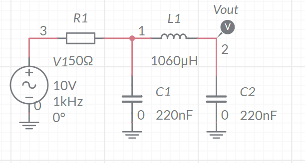
I have the LC circuit below. I believe (but I'm not certain) that this is a 3rd order filter. Since there are two capacitors and 1 inductor.

enter image description here

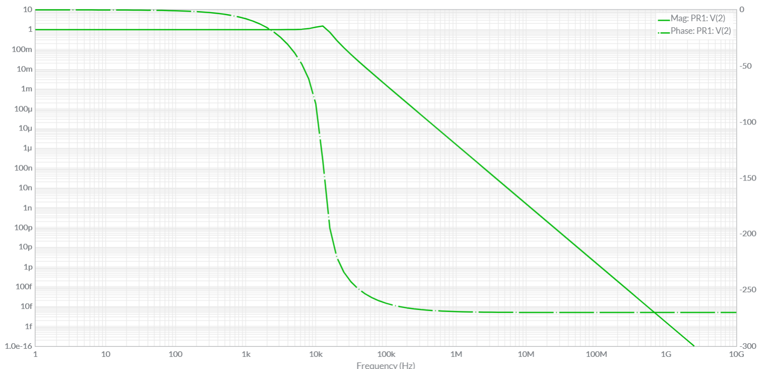
The circuit is a passive low pass pi filter. The component values have been chosen so that the cutoff frequency is 15kHz. The input is from a signal generator with a source impedance of 50ohms (the resistor shown).

I need to derive a transfer function for the circuit but I'm not sure how, since I don't know the order of the system. The Bode plots of the system are below: enter image description here Can anyone help me derive the transfer function of the system using these Bode plots?

\$\endgroup\$
6
  • \$\begingroup\$ You don't need to know the order to derive the TF - just a couple of pages of Laplace orientated math. Working from the bode plot is not sensible nor accurate. Do the math. \$\endgroup\$
    – Andy aka
    Commented Apr 28, 2020 at 11:12
  • 2
    \$\begingroup\$ Small note regarding your schematic, for future, pay attention to draw a clean schematic: I first read the value of R1 as 150Ω. Do also remove the superfluous 0 next to the ground nodes. \$\endgroup\$
    – Huisman
    Commented Apr 28, 2020 at 11:38
  • 1
    \$\begingroup\$ There are 3 independant energy buffers being 2 capacitors and 1 inductor, so it is third order. \$\endgroup\$
    – Huisman
    Commented Apr 28, 2020 at 11:40
  • 1
    \$\begingroup\$ Yes, this is a 3rd-order circuit and you can try to apply the fast analytical circuits techniques to this filter. \$\endgroup\$ Commented Apr 28, 2020 at 11:43
  • \$\begingroup\$ "Can anyone help me derive the transfer function of the system using these Bode plots?" Sure, hit the edit link and show how far you come. We're happy to help. \$\endgroup\$
    – Huisman
    Commented Apr 28, 2020 at 11:53

3 Answers 3

4
\$\begingroup\$

If you do the algebra (it's amazing what folk will do in lock-down of course) you get the following transfer function: -

$$H(s) = \dfrac{1}{s^3LC_1C_2R + s^2LC_2 + sR(C_1+C_2) + 1}$$

And just to demonstrate that is correct I used micro-cap 12 and the following circuit: -

enter image description here

Inside the red box is the input AC voltage that can be swept from low to high frequencies. To the left of that is the conventional circuit formed by R, L, C1 and C2.

To the right we have micro-caps 12's Laplace function solver. Both circuits are fed from V1 (red box).

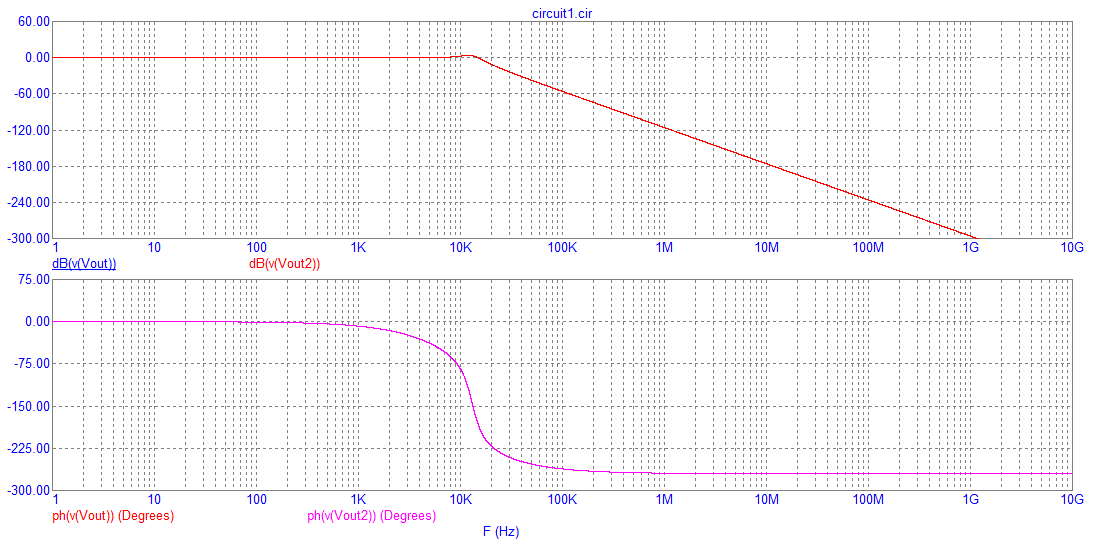
Comparing both bode plots we get identical overlapping results: -

enter image description here

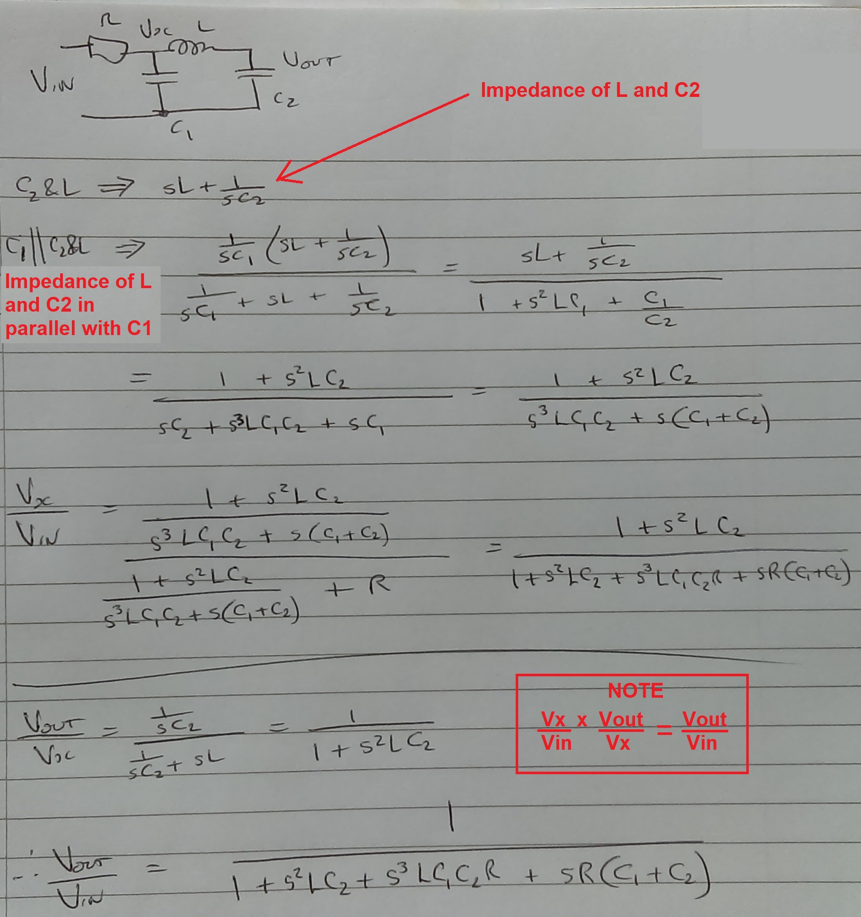
If this helps then that's good. If you require the derivation of the above TF then ask. I don't suppose it hurts to post my reasonably legible hand calcs: -

enter image description here

\$\endgroup\$
3
\$\begingroup\$

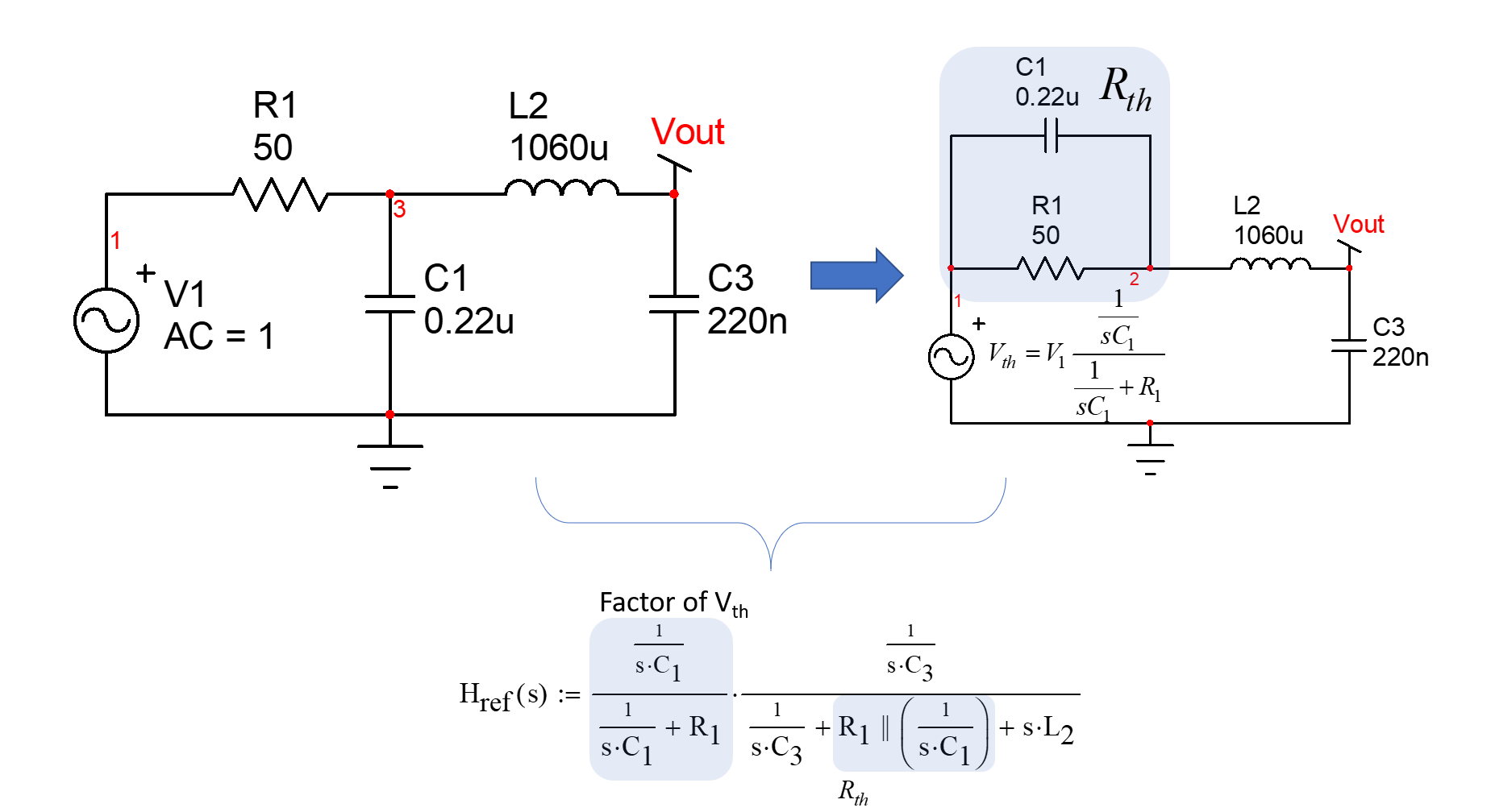
This transfer function can be obtained using brute-force analysis or the fast analytical circuit techniques known as FACTs. For the brute-force approach, you can consider a Thévenin generator featuring the first \$RC\$ filter driving the \$LC\$ network. If you do the maths ok, you should find:

enter image description here

Then you develop all the terms and rearrange to form a 3rd-order polynomial to reveal resonant and cutoff frequencies. The other option is to use the FACTs which will lead you to the coefficients values in one shot, without equations and the risk to make mistakes while developing the above expression. Just go through the time constants determination as shown in the below drawing and you find the transfer function very quickly:

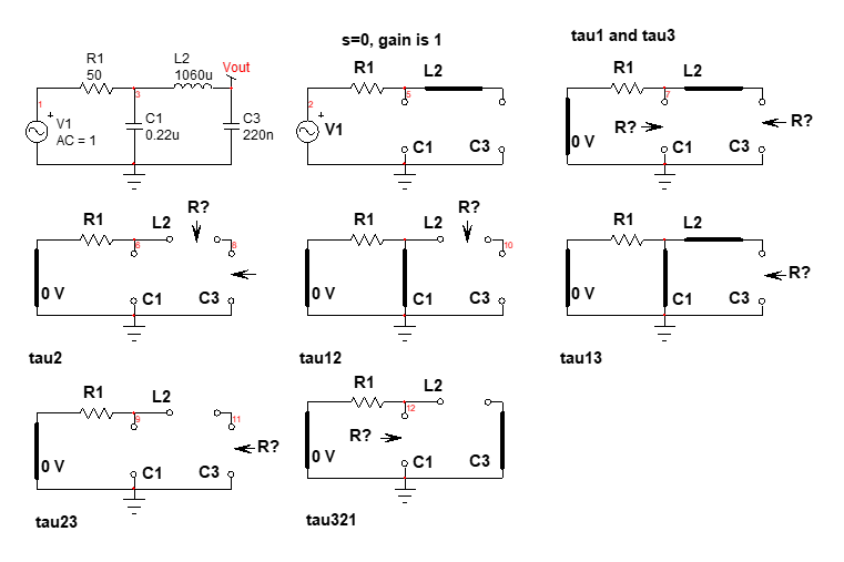
enter image description here

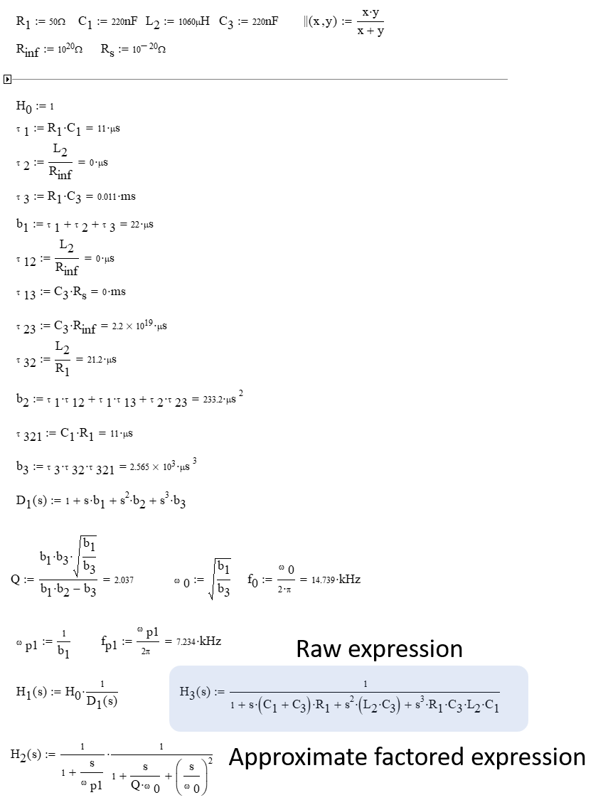
Assemble the time constants in a Mathcad sheet and try to factor the 3rd-oder polynomial with a 1st-order filter dominating the low-frequency response:

enter image description here

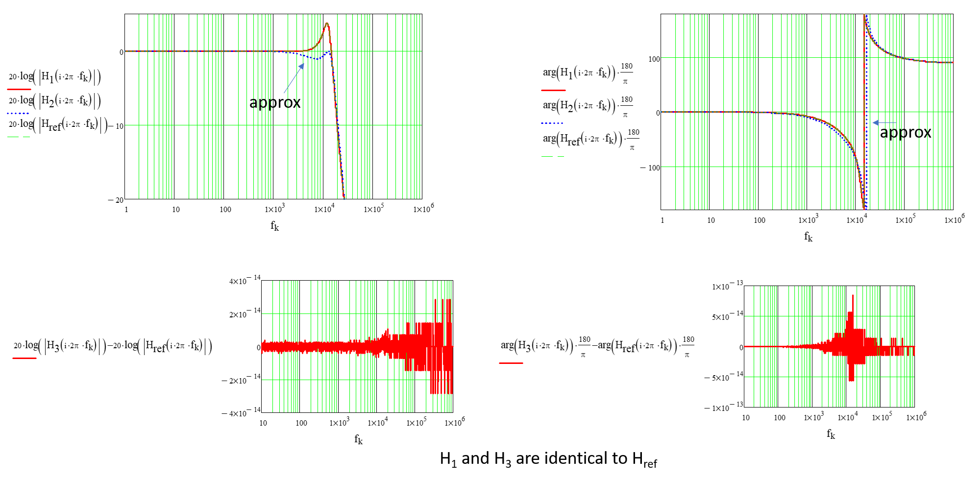
And finally you can plot the ac response. Please note the divergence of the factored expression. This is because the \$RC\$ cutoff frequency is too close to the double poles incurred by the \$LC\$ filter. Increasing \$R_1\$ to 100 \$\Omega\$ gives a better fit:

enter image description here

\$\endgroup\$
0
\$\begingroup\$

First, I will present a method that uses Mathematica to solve this problem. When I was studying this stuff I used the method all the time (without using Mathematica of course).

Well, we are trying to analyze the following circuit:
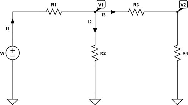
schematic

simulate this circuit – Schematic created using CircuitLab

When we use and apply KCL, we can write the following set of equations:

$$\text{I}_1=\text{I}_2+\text{I}_3\tag1$$

When we use and apply Ohm's law, we can write the following set of equations:

$$ \begin{cases} \text{I}_1=\frac{\text{V}_\text{i}-\text{V}_1}{\text{R}_1}\\ \\ \text{I}_2=\frac{\text{V}_1}{\text{R}_2}\\ \\ \text{I}_3=\frac{\text{V}_1-\text{V}_2}{\text{R}_3}\\ \\ \text{I}_3=\frac{\text{V}_2}{\text{R}_4} \end{cases}\tag2 $$

Substitute \$(2)\$ into \$(1)\$, in order to get:

$$ \begin{cases} \frac{\text{V}_\text{i}-\text{V}_1}{\text{R}_1}=\frac{\text{V}_1}{\text{R}_2}+\frac{\text{V}_1-\text{V}_2}{\text{R}_3}\\ \\ \frac{\text{V}_\text{i}-\text{V}_1}{\text{R}_1}=\frac{\text{V}_1}{\text{R}_2}+\frac{\text{V}_2}{\text{R}_4} \end{cases}\tag3 $$

Now, we can solve for the transfer function:

$$\mathcal{H}:=\frac{\text{V}_2}{\text{V}_\text{i}}=\frac{\text{R}_2\text{R}_4}{\text{R}_1\left(\text{R}_2+\text{R}_3+\text{R}_4\right)+\text{R}_2\left(\text{R}_3+\text{R}_4\right)}\tag4$$

Where I used the following Mathematica-code:

In[1]:=Clear["Global`*"];
FullSimplify[
 Solve[{I1 == I2 + I3, I1 == (Vi - V1)/R1, I2 == V1/R2, 
   I3 == (V1 - V2)/R3, I3 == V2/R4}, {I1, I2, I3, V1, V2}]]

Out[1]={{I1 -> ((R2 + R3 + R4) Vi)/(R2 (R3 + R4) + R1 (R2 + R3 + R4)), 
  I2 -> ((R3 + R4) Vi)/(R2 (R3 + R4) + R1 (R2 + R3 + R4)), 
  I3 -> (R2 Vi)/(R2 (R3 + R4) + R1 (R2 + R3 + R4)), 
  V1 -> (R2 (R3 + R4) Vi)/(R2 (R3 + R4) + R1 (R2 + R3 + R4)), 
  V2 -> (R2 R4 Vi)/(R2 (R3 + R4) + R1 (R2 + R3 + R4))}}

When we want to apply the derivation from above to your circuit we need to use Laplace transform (I will use lower case function names for the functions that are in the (complex) s-domain, so \$\text{y}\left(\text{s}\right)\$ is the Laplace transform of the function \$\text{Y}\left(t\right)\$):

  • $$\text{R}_2=\frac{1}{\text{sC}_1}\tag5$$
  • $$\text{R}_3=\text{sL}\tag6$$
  • $$\text{R}_4=\frac{1}{\text{sC}_2}\tag7$$

So, we can rewrite the transfer function as:

$$\mathscr{H}\left(\text{s}\right)=\frac{\frac{1}{\text{sC}_1}\cdot\frac{1}{\text{sC}_2}}{\text{R}_1\left(\frac{1}{\text{sC}_1}+\text{sL}+\frac{1}{\text{sC}_2}\right)+\frac{1}{\text{sC}_1}\cdot\left(\text{sL}+\frac{1}{\text{sC}_2}\right)}=$$ $$\frac{1}{\text{C}_1\text{C}_2\text{L}\text{R}_1\text{s}^3+\text{C}_2\text{L}\text{s}^2+\text{R}_1\left(\text{C}_1+\text{C}_2\right)\text{s}+1}\tag8$$

Now, when working with sinusoidal signals we can use \$\text{s}:=\text{j}\omega\$ (where \$\text{j}^2=-1\$ and \$\omega=2\pi\text{f}\$ with \$\text{f}\$ is the frequency of the input signal in Hertz). So we get:

$$\underline{\mathscr{H}}\left(\text{j}\omega\right)=\frac{1}{\text{C}_1\text{C}_2\text{L}\text{R}_1\left(\text{j}\omega\right)^3+\text{C}_2\text{L}\left(\text{j}\omega\right)^2+\text{R}_1\left(\text{C}_1+\text{C}_2\right)\text{j}\omega+1}=$$ $$\frac{1}{-\text{C}_1\text{C}_2\text{L}\text{R}_1\omega^3\text{j}-\text{C}_2\text{L}\omega^2+\text{R}_1\left(\text{C}_1+\text{C}_2\right)\omega\text{j}+1}=$$ $$\frac{1}{1-\text{C}_2\text{L}\omega^2+\text{R}_1\omega\left(\text{C}_1+\text{C}_2\left(1-\text{C}_1\text{L}\omega^2\right)\right)\text{j}}\tag9$$

So, the absolute value of the transfer function is given by:

$$\left|\underline{\mathscr{H}}\left(\text{j}\omega\right)\right|=\frac{1}{\sqrt{\left(1-\text{C}_2\text{L}\omega^2\right)^2+\left(\text{R}_1\omega\left(\text{C}_1+\text{C}_2\left(1-\text{C}_1\text{L}\omega^2\right)\right)\right)^2}}\tag{10}$$
\$\endgroup\$

Your Answer

By clicking “Post Your Answer”, you agree to our terms of service and acknowledge you have read our privacy policy.

Not the answer you're looking for? Browse other questions tagged or ask your own question.