2
\$\begingroup\$

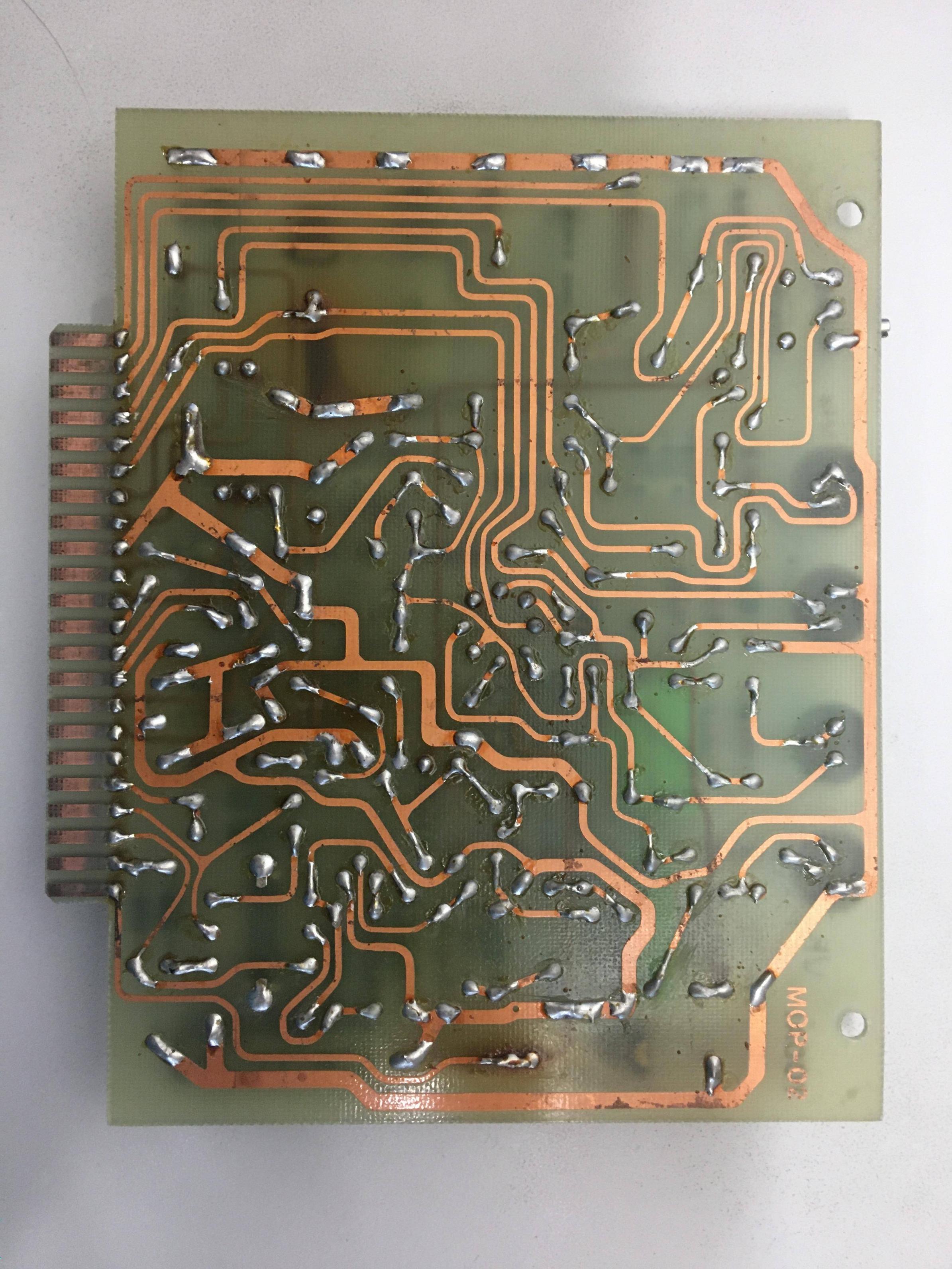
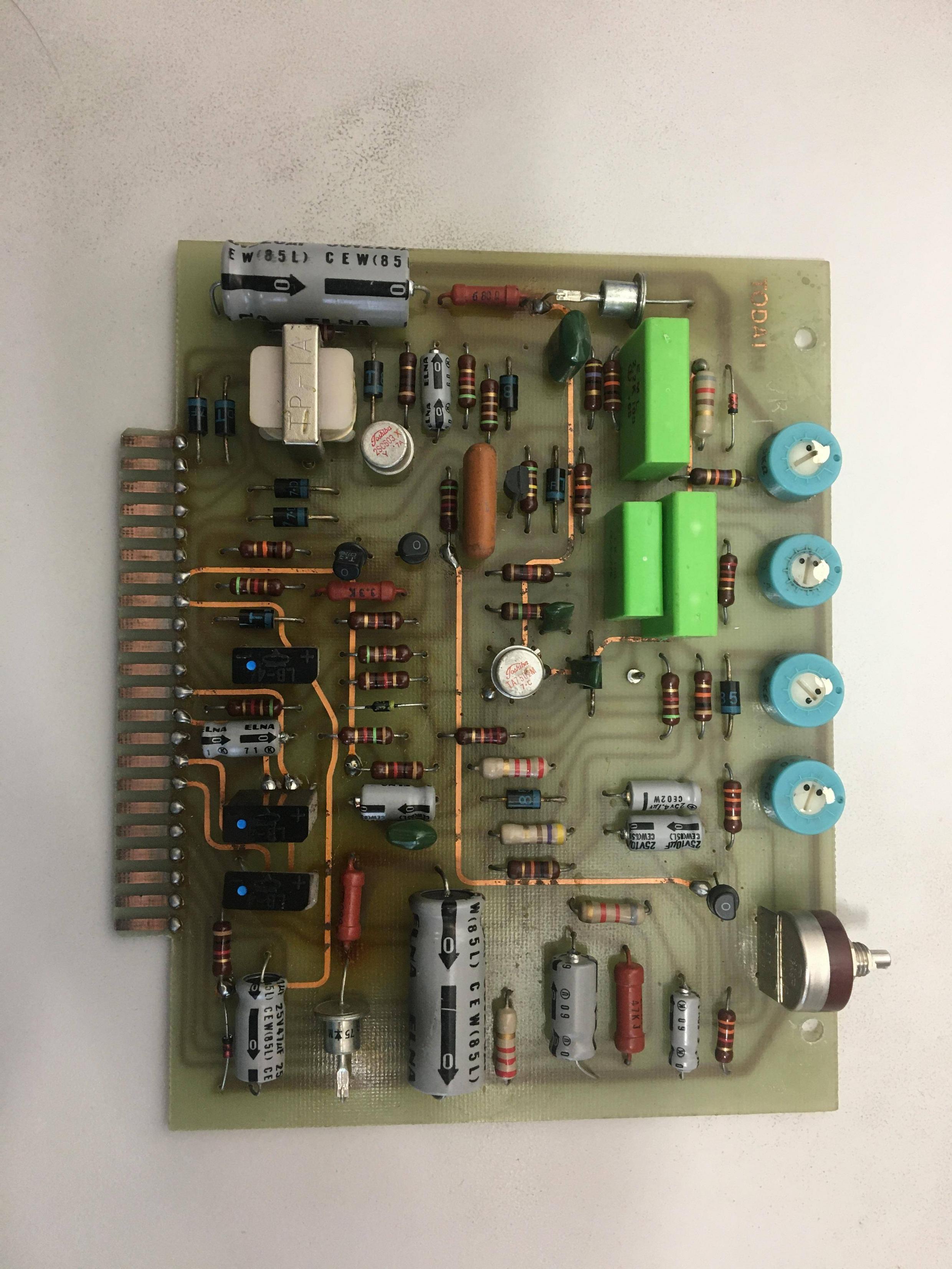
This board performs the speed control logic for a 3 HP shunt-wound DC motor driver in a CNC mill built in 1979. The spindle turned on intermittently last week and then stopped working, so I'm reverse engineering the circuit to debug it.

I've ID'd everything except these three black components with the blue dots near the card edge connector. They each have four leads, and the only markings are "LB-4", a little chat bubble like logo, and +, - markings for two of the leads.

There's no continuity between any of the leads. Can anyone help me identify these?

I'm also not certain about the three big green bricks. They seem to just be power resistors but the markings on them say E M L 2.2K 100 (logo) 0.60 for the large two and 1K 100 (logo) E.776 for the small one, where (logo) is a little downward arrow in a circle. What has me skeptical about the 'power resistor' guess is that they measure more than 2.2 kohms. Circuit image
Edit: Back image:

back image

\$\endgroup\$
4
  • 1
    \$\begingroup\$ Can you add a picture of the other side? Is that resistor on the bottom left burnt? \$\endgroup\$
    – Alphy13
    Commented May 1, 2020 at 3:40
  • \$\begingroup\$ @Alphy13 just added a link to one above: imgur.com/a/Z2FJcai See also this version with the back layer traced and overlaid: imgur.com/a/vy5FObm \$\endgroup\$ Commented May 1, 2020 at 3:54
  • 1
    \$\begingroup\$ Bridge rectifiers. \$\endgroup\$
    – user16324
    Commented May 1, 2020 at 10:36
  • \$\begingroup\$ The legend "Todai" might suggest a connection to Tokyo University \$\endgroup\$
    – user16324
    Commented May 1, 2020 at 10:39

6 Answers 6

4
\$\begingroup\$

Those black components look like bridge rectifiers to me.

The resistor in the bottom left looks burned out. Try replacing that first.

Excellent job overlaying the mask you added to the latter image.

\$\endgroup\$
5
\$\begingroup\$

I agree, they look like bridge rectifiers (+1). They probably go to individual transformer windings (the center pairs of connections). You can check the inputs and outputs. They are unlikely to be bad, but it's possible. At least two rails appear to be zener shunt-regulated with the power dropping resistors (discolored PCB under them) and top-hat diodes.

Design looks older than 1979 but with some newer parts. Weird hand-made Japanese-looking sort of, but no plated-through holes and no gold plating on the connector pins, very cruddy. If I were to guess I'd say ca. 1970 Taiwanese design.

If the electrolytic capacitors are that old, they're all suspect, particularly the two larger ones. Check the ESR or just replace them.

The green "bricks" are film capacitors.

\$\endgroup\$
4
  • 3
    \$\begingroup\$ +1 for the caps, if they are that old, replace them. \$\endgroup\$
    – Alphy13
    Commented May 1, 2020 at 4:27
  • 1
    \$\begingroup\$ Thanks for the help you two! The relevant board edge connections go to some transformers I've been scratching my head about down in the controller so you're most likely right about rectifiers. The diode test results are a little odd but I bet if I draw a picture it'll show a bridge rectifier. \$\endgroup\$ Commented May 1, 2020 at 4:49
  • 1
    \$\begingroup\$ @NickParker What country was this CNC controller made in? \$\endgroup\$ Commented May 1, 2020 at 5:05
  • 2
    \$\begingroup\$ The Japanese comment was a good guess! It's a Shizuoka ST-N from Japan. It was retrofitted with a Bandit III in California around 1979, but this board is part of the original Todai DC Motor Control Pack. \$\endgroup\$ Commented May 1, 2020 at 5:10
0
\$\begingroup\$

I agree on the electrolytics (test them or replace them) & that the green components are caps.

I might be missing something but the black components with blue dots only have two pins and there are only three of them so they can't be bridge rectifier either together or separately. I would think they are just diodes that are big enough to carry some current. All three of them seem to just be connected to the edge connector pins.

\$\endgroup\$
0
\$\begingroup\$

First of all why don't t you try to fix those corroded trace lines. Use the soldering iron and some solder to plate them and measure continuity.. Then measures those resistors where you see the overheating areas. Use a pencil eraser to clean both sides of the edge connector. Measure all active and passive components. Retest it

\$\endgroup\$
0
\$\begingroup\$

First guess is that they are MOV or TVS devices for suppression of noise and spikes on long cables to the motor; once you figure out the schematic it may become obvious.

\$\endgroup\$
0
\$\begingroup\$

Black components are bridge rectifier. The green components are capacitors 2.2 uF and 1uF 100v. You problem is the cooper traces, if you check continuity you will find some open.

\$\endgroup\$

Not the answer you're looking for? Browse other questions tagged or ask your own question.