I am designing a 6th-order multiple feedback low-pass filter with the cut-off frequency at 1000 Hz. I wrote a Matlab script that calculated the capacitor and resistor values.
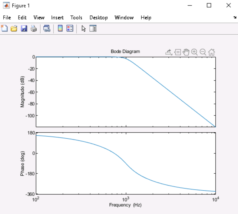
I combined all transfer functions together and got a Bode plot with exactly 1000 Hz as the cut-off frequency, with 6th-order roll-off. FYI: the gain K = 1.
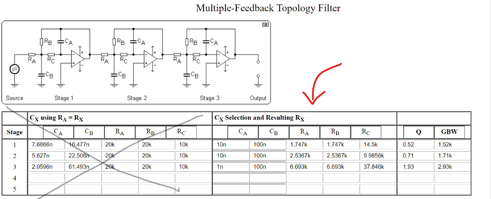
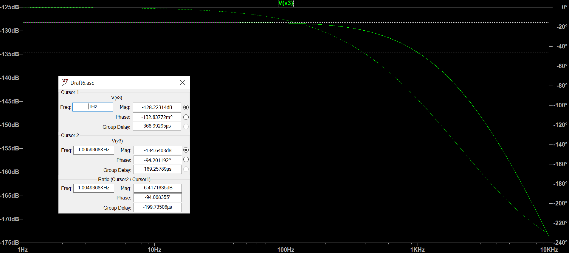
I even checked it with an online Butterworth multiple feedback low-pass calculator and got the exact same values. Now, when I build the schematic in LTSpice, the cut-off frequency is skewered and I cannot figure out why.
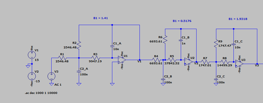
Either something about the multiple feedback topology is the issue, or I am missing something in LTspice. Any solutions or explanations to why LTspice is not giving me the correct Bode response? Down below is my MATLAB plot, the online filter calculator, and my LTspice schematic and Bode plot.


