1
\$\begingroup\$

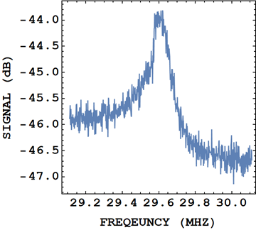
I'm working with some parallel RCL circuits and I have noted that when I record a power spectrum (so \$\rm{dB}\$ vs \$\rm{Hz}\$) that the spectrum is asymmetric:

enter image description here

As I'm sure you all know if we calculate the impedance of a parallel RCL circuit
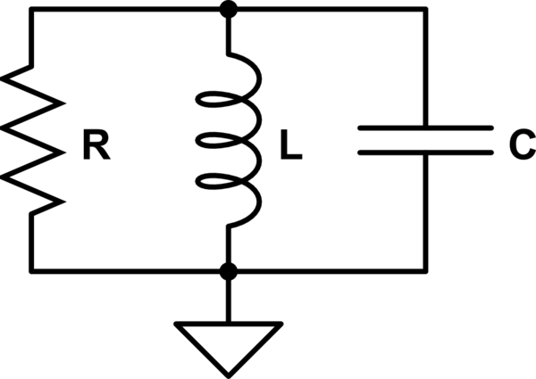
schematic

simulate this circuit – Schematic created using CircuitLab

we get $$ z_{\rm{RCL}} = \frac{i L R \omega}{R + i L \omega - C L R \omega^{2}} $$

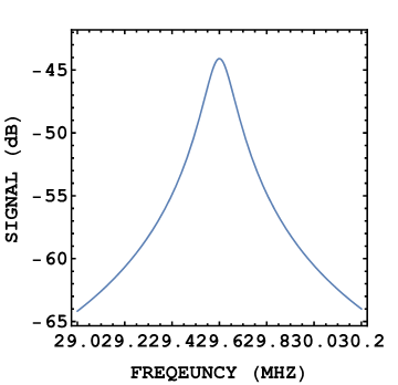
and if we take the real-part of this then we get $$ {\rm{Re}}\left(z_{\rm{RCL}} \right) = \frac{1}{R \left(\frac{1}{R^{2}} + \left( \frac{1}{L \omega} - C\omega \right)^{2} \right)}$$ which just by looking at we can tell is symmetric. But if we plot it:

enter image description here

So my first question is: Where does this asymmetry come from?

My first guess is that this is parasitic inductances and capacitances.

So my first question is: how can I adjust my equation to consider these asymmetries so I can do better fits?

My end goal is to extract the \$Q\$-factor and resonance frequency.


Further research and comments

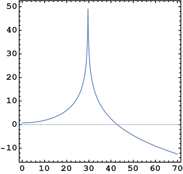
Some additional comments since having an answer. The circuit proposed in the answer below is indeed a better fit, $${\rm{Re}}(Z) = \frac{R}{1 + C \omega^{2} (C R^{2} + L (C L \omega^{2} - 2))}$$ and is asymmetrical in the direction that is shown by my data. However there seems to be other components at work as the tilt in my data seems to be more extreme than is represented by the lineshape as described above.

enter image description here

In the graph above we can see the data, which I have linearised, add the lineshape as shown above. While the asymmetry is present (if I plot to large frequency spans) it seems to have a quite small sensitivity to frequency scaling, which makes me wonder if parasitic inductances and capacitances would adjust this.

Just for clarity here is the new lineshape showing the asymmetry better in logarithmic units:

enter image description here

\$\endgroup\$
11
  • \$\begingroup\$ You haven't demonstrated that your applied spectrum is flat. Neither have you shown how you apply the spectrum of noise to your filter. \$\endgroup\$
    – Andy aka
    Commented May 2, 2020 at 10:15
  • \$\begingroup\$ @Andyaka What do you mean by flat? \$\endgroup\$
    – user27119
    Commented May 2, 2020 at 10:16
  • \$\begingroup\$ Flat = equal power at all frequencies. Show your circuit too. \$\endgroup\$
    – Andy aka
    Commented May 2, 2020 at 10:16
  • \$\begingroup\$ How would one demonstrate that? I'm happy to add the circuit, but I'm not sure what that adds? It's a parallel RCL circuit, or are you interested in how the excitation is applied? \$\endgroup\$
    – user27119
    Commented May 2, 2020 at 10:20
  • 2
    \$\begingroup\$ @Q.P., Andyaka means that you can also include a graph with C and L disconnected. You must also include the source resistance of the noise source in your equivalent circuit. It might also be instructive to connect C and L separately and then show the spectrum. \$\endgroup\$
    – skvery
    Commented May 2, 2020 at 10:37

1 Answer 1

1
\$\begingroup\$

The RCL circuit is actually a shielded inductor, so a solenoid inside of a copper can essentially. The capacitance is parasitic coming from coil-to-coil and coil-to-shield interactions.

This means that the noise comes from the inductor's series resistance and therefore is not parallel to the inductor but in series: -

schematic

simulate this circuit – Schematic created using CircuitLab

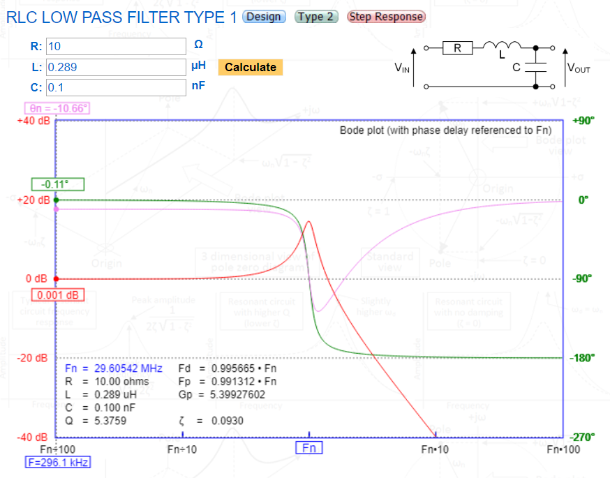
For the above (and below) I've made an estimate of the R, L and C values to roughly match the peak in the response at 29.6 MHz.

If so, then the 2nd order filter characteristic is low pass and not band pass such as shown with this on-line simulator: -

enter image description here

The red trace above is the response of a low pass 2nd-order filter and not a band-pass filter - might it look familiar?

\$\endgroup\$
12
  • \$\begingroup\$ It absolutely does! What's interesting is that this is in the same functional form as a Fano Resonance, I was using this as a parametrisation, but your model is preferential as it represents physics! Thanks! \$\endgroup\$
    – user27119
    Commented May 2, 2020 at 11:45
  • \$\begingroup\$ I have no-idea what Fano resonance is but if it helps, that's good. \$\endgroup\$
    – Andy aka
    Commented May 2, 2020 at 11:47
  • \$\begingroup\$ I have one final question if you are willing. If I add further orders, so additional inductances and capacitances in parallel would this affect the skew any further? \$\endgroup\$
    – user27119
    Commented May 2, 2020 at 12:44
  • 1
    \$\begingroup\$ Yes it might - you could use the simulation tool I linked and, for two stages, you would half the resistance, half the inductance and double the capacitance to get equivalence in terms of frequency response. \$\endgroup\$
    – Andy aka
    Commented May 2, 2020 at 12:51
  • 1
    \$\begingroup\$ @Q.P. Just make sure that it doesn't take anything away from the original question - add it under a title such as "edit section" or "further research information". I say this because someone coming along later might think I've not adequately answered you "fuller" question and might give me downvotes. \$\endgroup\$
    – Andy aka
    Commented May 2, 2020 at 13:10

Your Answer

By clicking “Post Your Answer”, you agree to our terms of service and acknowledge you have read our privacy policy.

Not the answer you're looking for? Browse other questions tagged or ask your own question.