0
\$\begingroup\$

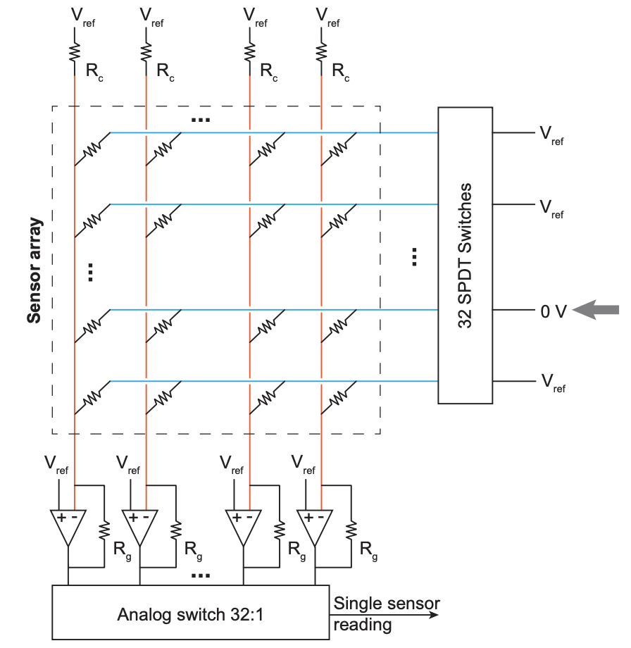
I need to find the output at the amplifier in the first column. The row with the grey arrow indicates that we have switched to ground, from what was initially Vref. I thought I could treat it as a voltage divider with R_c and the row resistor as the terms.

It's a circuit from a research paper, but the equation is not provided.

So what is the single sensor reading? Which is essentially the voltage from the amplifier in column one and the second to last row... I'm really just trying to derive an equation wherein I can solve for the variable row resistor.

enter image description here

\$\endgroup\$
9
  • \$\begingroup\$ You've forgotten to ask a question. \$\endgroup\$
    – brhans
    Commented May 14, 2020 at 15:55
  • \$\begingroup\$ fixed? I forgot to attach the image. \$\endgroup\$ Commented May 14, 2020 at 15:57
  • \$\begingroup\$ It's not clear form your post where you're getting stuck (because you haven't asked a question). But if you ignore switch resistance then you can treat each column as a simple inverting summing amplifier. \$\endgroup\$
    – brhans
    Commented May 14, 2020 at 15:59
  • \$\begingroup\$ Ofc if you can't ignore the switch resistance then it gets a bit more ... interesting ... \$\endgroup\$
    – brhans
    Commented May 14, 2020 at 16:03
  • \$\begingroup\$ I can't ignore the switch resistance. I'm eventually trying to solve it given that I know Rc and Rg and Vref. \$\endgroup\$ Commented May 14, 2020 at 16:07

1 Answer 1

0
\$\begingroup\$

Op-amps have three basic properties: near infinite input impedance, near infinite open loop gain, and a virtual short between the two input terminals (when used with negative feedback). The short causes Vref to appear at the inverting (-) terminal of each op-amp. As a result, no current is flowing through Rc. However, when a switch is enabled, each of the sensor array resistors in that row can now conduct current. Where does this current come from? The op-amp's output through the feedback path. The final output from the analog switch comes from the current being drawn due to the sensor multiplied by Rg in the feedback path of the op-amp. In an equation:

V(read) = Rg * Vref/R(sensor)

\$\endgroup\$
2
  • 1
    \$\begingroup\$ "Op-amps have ... a virtual short between the two input terminals" when used with negative feedback. You might want to clarify that. Many of our readers get caught out with, for example, Schmitt triggers. \$\endgroup\$
    – Transistor
    Commented May 14, 2020 at 17:32
  • \$\begingroup\$ Good point. Thanks for the update! \$\endgroup\$
    – nate
    Commented May 14, 2020 at 17:35

Your Answer

By clicking “Post Your Answer”, you agree to our terms of service and acknowledge you have read our privacy policy.

Not the answer you're looking for? Browse other questions tagged or ask your own question.