2
\$\begingroup\$

I'm creating a SMD PCB where space is extremely limited. Usually, the application is powered by a battery (Single cell 3.7v lipo). To charge the battery, I'm using a USB cable.

What I'd like is for the application to automatically switch to USB power instead of the battery whenever power from the USB is present.

A normally closed "switch" between the battery and load sounds ideal. The +5v from the USB would be used to open the switch. When the USB is disconnected (left floating) the switch would close and connect the battery again. Is there a simple way to achieve this? Am I overcomplicating it - would a diode on the positive terminal of the battery serve the same purpose?

As I say, space is extremely limited so I'm trying to achieve this with as few components as possible. I'm hoping I can find a single solution in say a SOT23 package or similar.

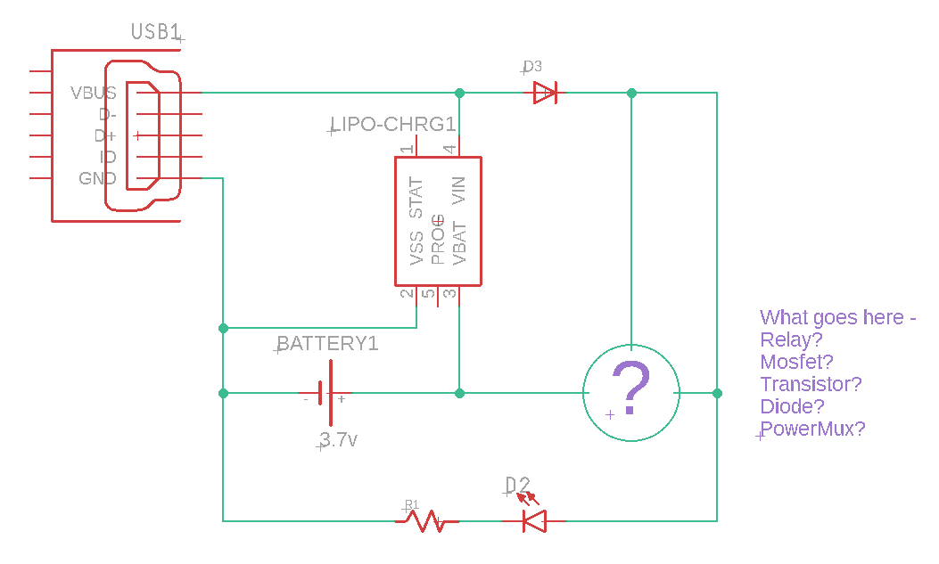
Here is a simplified schematic drawing.

The problem - how to automatically disconnect battery when USB power is present

\$\endgroup\$
1
  • 1
    \$\begingroup\$ Depends on the supply voltage requirement of your application. If it can tolerate the voltage drop, just a pair of diodes will do the job. \$\endgroup\$
    – Finbarr
    Commented May 21, 2020 at 19:13

3 Answers 3

1
\$\begingroup\$

There are IC's designed specifically for this, and in small packages too. One example is TPS2113A from TI. The TPS2121 is another option if you need higher current. Other suppliers like Maxim make devices as well. Search for "power mux IC".

\$\endgroup\$
3
  • 1
    \$\begingroup\$ There are also charger IC's which separate the battery from the load. So there is a load connection, a USB connection and a battery connection and the charger itself manages power flow. \$\endgroup\$
    – user57037
    Commented May 21, 2020 at 21:30
  • \$\begingroup\$ This looks like a very attractive solution @BrianB. Thank you. I just need to work out my power consumption now. If you get a moment, please see my comment in reply to Big6's answer. \$\endgroup\$ Commented May 22, 2020 at 14:55
  • \$\begingroup\$ This worked perfectly and only required the addition of one extra component. Thank you @BrianB \$\endgroup\$ Commented May 31, 2020 at 10:05
3
\$\begingroup\$

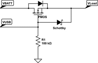
You can try this:

schematic

simulate this circuit – Schematic created using CircuitLab

It only requires 3 components: A PMOS, a Schottky, and a pull-down resistor.

  1. When VBATT is present and VUSB is not, then the PMOS will be ON, initally through the body diode, but eventually through its on-resistance, once Vgs is enough to turn it on. Pick a PMOS that will turn on fully 3.3V. The PMOS will keep the voltage drop lower (I*Rds(ON)), under normal conditions, than a diode, so it saves some of the battery voltage from going to waste.

  2. When VUSB is present, it does not matter whether VBATT is present or not, because it will keep the PMOS OFF (Vg > Vs) and the load will be powered from VUSB through the Schottky.

Notice the orientation of the PMOS. The body diode will keep VUSB from inadvertently sourcing current the battery and creating a safety issue.

\$\endgroup\$
5
  • 1
    \$\begingroup\$ It is considered bad form to make a net connection at a 4-way right angle cross. I totally misread your schematic initially, not realizing that VUSB connected to the gate of the MOSFET. It would be good in future to offset one of the lines slightly so that you have two three-way connections (if that makes sense). \$\endgroup\$
    – user57037
    Commented May 21, 2020 at 21:07
  • 1
    \$\begingroup\$ @mkeith Thanks for the feedback, I missed that, that's one of the things I make sure I enforce in my schematics. \$\endgroup\$
    – Big6
    Commented May 21, 2020 at 21:21
  • \$\begingroup\$ Thanks @Big6. Appreciated! \$\endgroup\$
    – user57037
    Commented May 21, 2020 at 21:28
  • \$\begingroup\$ Thanks @Big6, I'd tried this myself but was missing the pulldown resistor. Could I ask another question regarding my power consumption: I have a 1.5w speaker (2ohm). Battery supply is 4.2v to 3.2v. So, at 3.2v the speaker is using 0.469 (1.5 / 3.2) amps. Or 469mA. Is that correct? \$\endgroup\$ Commented May 22, 2020 at 14:53
  • \$\begingroup\$ @GlynDavidson Yes, I think so. I got hung up on some numbers, but yes, P/V gives the current being sourced to the load. \$\endgroup\$
    – Big6
    Commented May 22, 2020 at 15:53
0
\$\begingroup\$

This might have been useful too - A CPC1114N solid state relay but max current is 400mA which I don't think is suitable for my particular project.

\$\endgroup\$

Your Answer

By clicking “Post Your Answer”, you agree to our terms of service and acknowledge you have read our privacy policy.

Not the answer you're looking for? Browse other questions tagged or ask your own question.