9
\$\begingroup\$

First, for those unfamiliar with the game, this is how the game works,

game play

The goal of the game is to turn off all the lights, hence called "Lights Out", and each press of the button/light inverses its state as well as its north/south/east/west adjacent neighbors, and that's pretty much it.

Now, what I could think of is by using SR flip-flops, or JK flip flops. This is due to its ability to act as storage element (the initial state and next state). But I can't seem to think of ways to actually implement them.

Another idea is that each set of button and its adjacent (NSEW)button/lights will have its own truth table, like this:
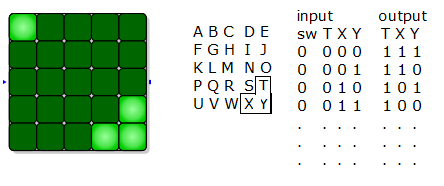
logic table

but, is it possible to have the input variables be the same as the output variables? Are there any other ways to do this?

\$\endgroup\$
0

3 Answers 3

9
\$\begingroup\$

The obvious approach would be to use a processor and do all this in firmware.

However, if I really needed to do this with stone knives and bear skins for some reason, I'd dedicate a toggling flip-flop to each square. The flip flop of each square would be toggled by the press of its button or either of the four neighboring buttons. Of course those button presses need to be de-bounced. Again, this would be easier in firmware.

A hardware solution wouldn't be all that complex, but everything would be replicated 25 times, making it large and tedius to build.

Added:

Apparently the description above is not clear enough. Here is a diagram of what is in each cell:

The other 4 inputs to the NAND gate are driven from the debounced signals of the 4 surrounding buttons that are also supposed to toggle the state of this square. Likewise, the debounced signal from this button also goes to one of the NAND gate inputs of each of the 4 surrounding cells.

\$\endgroup\$
8
  • 1
    \$\begingroup\$ This sounds like the most feasible thing to do. I'd use TFFs and tie all the T inputs to "1.". Then I'd have a SPDT momentary switch for each button. Tie one throw to "0," one throw to "1," and then the pole to the corresponding TFF clock inputs. Then, when you press a switch, it will toggle the surrounding flip-flops by generating a single pos/neg edge. \$\endgroup\$
    – Shamtam
    Commented Dec 1, 2012 at 18:30
  • 1
    \$\begingroup\$ @Shamtam: Yes, that's one way of debouncing if you have SPDT switches. Most pushbuttons however are just normally open SPST. \$\endgroup\$ Commented Dec 1, 2012 at 20:54
  • \$\begingroup\$ I guess I'd have to use SPDT switch for debouncing, whether pushbutton or not. I get now how to connect the inputs of this game, but what I don't get is how to connect the outputs to the LEDs. I mean, it can't be just simple output (Q) to the LED and its neighbors the complement(Q') right? Also, another question, do I need to use the clock signal input of the TFF? If so, how? \$\endgroup\$
    – Julienn
    Commented Dec 3, 2012 at 12:30
  • 2
    \$\begingroup\$ The flipflop for each cell drives its LED directly. The logic having to do with neighboring cells enters into the input to the flipflip, but the output stays local to the cell. No, SPDT switches are not required for debouncing. There are various techniques for debouncing a single signal like from a SPST switch. \$\endgroup\$ Commented Dec 3, 2012 at 14:51
  • 1
    \$\begingroup\$ No, you don't get the logic. Normally, the debounced outputs are high, so all inputs to the NAND gate are high, which drives the output low. When any button is pressed, that NAND get input goes low, making the NAND output go high. This low to high edge causes the FF to toggle its state. \$\endgroup\$ Commented Dec 4, 2012 at 16:51
0
\$\begingroup\$

I would say that T flip flops would probably be the easiest as you can toggle their output state with a single input. You could use a single flip flop for each LED and with the input tied to your button and the output tied to your LED. Then you could have each button tied to the inputs of the 4 adjacent flip flops in order to toggle their state as well.

If you wanted to use JK flip flops, you can make T flip flops out of them by passing your input to both of the inputs (J and K)

\$\endgroup\$
1
  • 2
    \$\begingroup\$ You could expand on your answer by explaining how you connect 5 switches to each flip-flop without having them interfere with each other. Also, what about switch bounce? \$\endgroup\$
    – Dave Tweed
    Commented Dec 1, 2012 at 18:18
0
\$\begingroup\$

If one wanted to build such a game up to size 7x7 out of discrete logic, the most practical design would probably be to use a circulating shift register to hold the state of the board, and a six-bit counter to keep track of the shift position of the data within the register. Shift data through the shifter in groups of 8 bits to drive a multiplexed display and scanned a multiplexed keyboard. Have a seven-bit "flip light" counter which will run any time the bottom six bits are non-zero, or when the state of the top bit matches the state of the presently-decoded button. Flip the state of the current light whenever all of the following apply:

6-bit counter isn't  xxx111
6-bit counter isn't  111xxx
7-bit counter isn't xxxxx00
7-bit counter isn't xx00xxx
7-bit counter is    00xx0xx

Note that while a significant amount of logic would be required to decode those counter states, it would be trivial compared to the number of chips required to implement each light separately.

\$\endgroup\$

Your Answer

By clicking “Post Your Answer”, you agree to our terms of service and acknowledge you have read our privacy policy.

Not the answer you're looking for? Browse other questions tagged or ask your own question.