While I can't fault Hufi's answer that directly addresses the specific questions asked, I'm not sure it explains the theory of operation of the circuit in a way that someone new to this kind of circuit can easily grasp. Once you understand the theory of operation of the circuit, you can answer those questions yourself.
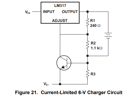
Probably the most important thing to keep in mind when analyzing this circuit is that the LM317 works kinda like a variable resistance that varies so as to regulate the output pin to be 1.25V higher than the adjust pin. When using it as a voltage regulator, we typically set the voltage at the adjust pin using a voltage divider across the output, but we can control the voltage at the adjust pin however we want and the LM317 will still work to keep the output pin about 1.25V higher than the voltage at the adjust pin.
The other thing that's handy to notice is that the output voltage - ie. the voltage across the battery being charged - is the voltage across the \$240\Omega / 1.1k\$ voltage divider. \$R_{3}\$ is not across the battery so if the transistor is off, the adjust pin is just set by the battery terminal voltage across the \$240\Omega / 1.1k\$ voltage divider. \$R_{3}\$ doesn't really matter in analyzing the LM317 as a voltage regulator in this circuit so long as the input voltage is enough to drive whatever current we expect through the LM317, the battery and \$R_{3}\$.
Consider what happens if the transistor is completely off - effectively open circuit. We have a typical LM317 voltage regulator circuit with the battery as the load and a voltage divider to set the output voltage. We know that the LM317 will act to keep 1.25V across the \$240\Omega\$ resistor, so the voltage across the entire voltage divider and hence across the battery is:
$$
V_{bat} = \frac{1.1k+240}{240} \times 1.25 = \frac{1340}{240} \times 1.25 \approx 6.97V
$$
Let's call that 7V.
Now let's look at what \$R_{3}\$ and the transistor do when we connect a battery that needs to be charged. To keep the numbers nice and round, I'm going to use \$R_{3}=0.6\Omega\$ and assume that the transistor needs about \$0.6V\$ across the base-emitter junction to start conducting.
It's also important to understand how a battery behaves when being charged. A battery in a low state of charge will have a lower terminal voltage and that voltage will rise as the state of charge increases. The terminal voltage will also rise depending on how much current we're forcing into the battery. If the transistor wasn't there, the current going into the battery would rise to the point where the terminal voltage equals about 7V. For the purpose of discussion, let's say that at the battery's current state of charge, 7V is enough to force about 3A of charge current into the battery. If we had 7V across the battery terminals, that 3A has to go through \$R_{3}\$, which means the voltage across \$R_{3}\$ would be about 1.8V. But this is also the base-emitter voltage of our transistor, so it must be turned on hard - effectively saturated and pulling the adjust pin down to about 0.6V. But this would mean that the LM317 output would only be around 1.85V (ie. 0.6V + 1.25V) and that's not enough to push any current into the battery, let alone 3A of charge current. Clearly we have a contradiction here so this can't be happening.
What we actually have here is another negative feedback loop formed by the LM317, the transistor, \$R_{3}\$ and the battery. What happens is that as the current through the battery rises, the voltage across \$R_{3}\$ rises. When the voltage across \$R_{3}\$ reaches 0.6V, it's enough to bias the transistor on and it starts to conduct. It can't turn on hard because that would shut off the charger output as we saw above. Instead we end up in a balancing act where the charge current through the battery ends up being just enough to turn the transistor on just enough to pull down the charger output voltage so that the charge current is just enough to keep the transistor turned on just a little bit... and round and round the loop we go. Since the transistor needs about 0.6V across the base-emitter junction to start conducting and I said that I would use \$R_{3}=0.6\Omega\$ this means that the charge current will be held constant at about 1A. If it tries to go slightly higher than that the transistor turns on more, forcing the LM317 to pull down the charge voltage and the charge current falls back to 1A. If the charge current falls slightly below 1A the transistor starts to turn off, allowing the LM317 to increase the charge voltage and correct the output current back up toward 1A again.
As the battery state of charge increases, the battery terminal voltage will slowly rise. All the while the feedback loop we talked about will keep pushing the charger output voltage up to keep the charge current at 1A. This continues until the battery terminals have 7V across them. Once that happens, the charger output voltage cannot go any higher. Why not? Because of the voltage divider across the battery. The voltage between the adjust and output pins of the LM317 is the voltage across that \$240\Omega\$ resistor. If the transistor is off, this is given by:
$$
V_{240\Omega} = \frac{240}{240+1.1k}V_{bat}=\frac{240}{1340}V_{bat}\approx0.18V_{bat}
$$
If \$V_{bat}=7V\$ then \$V_{240\Omega}\$ is about 1.253V. We're already a little higher than the 1.25V that the LM317's internal feedback is trying to maintain, so it will act to lower the output terminal voltage a little to bring it back into regulation.
Why did I suggest this with the transistor turned off? Because if the transistor is drawing any current at all, that increases the current through the \$240\Omega\$ resistor, increasing the voltage between the LM317's adjust and output pins. This makes the voltage regulation problem worse and drives the LM317 to lower the output voltage even more, so we just can't go above 7V at the output.
At this point, the battery state of charge has increased enough that 7V is no longer enough to push 1A of charge current into the battery. So the current starts falling below 1A. Since the LM317 can't push the voltage any higher, the voltage across \$R_{3}\$ and the transistor's base-emitter junction falls below 0.6V and the transistor turns off. We're now back at a standard LM317 voltage regulator circuit. As a voltage regulator, it holds the charger output voltage at 7V for the remainder of the charge cycle while the charge current continues to fall as the battery state of charge increases.
This is how CCCV chargers work. They're basically just a power supply that operates to a maximum voltage and current limit with the output rising to whichever of those limits is hit first and that's all this circuit does. They often have additional smarts built in to keep track of the state of charge and shut off the charging at some point - or perhaps other things. But at their core, they're just some kind of power supply with a current and voltage limit. For this particular circuit, the voltage limit is set by the voltage divider across the battery and the current limit is set by \$R_{3}\$. \$R_{3}\$ will probably be selected within the range of about \$0.4\Omega\$ to about \$6\Omega\$, depending on what maximum charge current is desired.
Is this suitable for lithium based battery chemistries? With appropriate resistors it could perform the CCCV function of a lithium battery charger, but at a minimum it should also include something to detect the end of charge condition and ideally a number of other protection features. You can buy specialized lithium battery charging ICs that integrate all the functions you need in one package. This makes something like this comparatively impractical but in a pinch could be designed to provide the CCCV function for lithium based chemistries. As shown in the schematic, this looks like it was designed for a 3-cell lead acid battery, as they have a nominal cell voltage of about 2V per cell, so 6V for a 3-cell battery. They also typically use a charge voltage of about 2.4V per cell, or around 7.2V for a 3-cell battery. This is pretty close to what the above resistor divider values give you and the caption does say it's for a 6V battery charger. If you were trying to charge lithium based cells, you'd need to check the datasheet for your cells and use resistors to set the voltage and current limits accordingly. Lead-acid batteries are much more forgiving to abuse during charging. Lithium based chemistries... not so much. If abused enough, they can sometimes catch fire and/or explode. If in doubt, you would want to err on the lower side for the maximum charge voltage. Using a lower CV will mean ending on a lower SOC, but also less likely to cause the cell to fail in some way due to overcharging.


