0
\$\begingroup\$

I am using the STM32f030C8T6 MCU on a custom PCB. I have 2 inputs on pins PB2 and PB0, wierldy enough, when these pins become high the MCU resets.

I had 2 assumption:

1: this somehow causes the reset pin to go low i.e. hardware problem but I hooked the pin to my scope and it stays HIGH (reset is active low)

2: there is something wrong with the GPIOB register, but i set another pin from GPIOB as an input and it works fine and doesn't suddenly restrart.

I use the HAL library and cubemx to define the state of the pins. the code i put in is as simple as follows:

while(1){
    check = HAL_GPIO_ReadPin (GPIOB, GPIO_PIN_0);
          if(check){
          for(i=0;i<3;i++){
                  HAL_GPIO_WritePin (GPIOB, GPIO_PIN_6, GPIO_PIN_SET);
                  HAL_Delay(1000);
                  HAL_GPIO_WritePin (GPIOB, GPIO_PIN_6, GPIO_PIN_RESET);
                  HAL_Delay(1000);
              }
          }
}

It's just to indicate what happens since there is an LED connected to pin 6. I ran the same code just with a different pin from port B (GPIOB) and it worked fine, I am trying to understand the cause of this unwanted restart. I tried it on both pins PB0 and PB2 and both result in a reset.

Below is the picture of the schematic used: enter image description here

Any help would be greatly appreciated.

\$\endgroup\$
6
  • 2
    \$\begingroup\$ Sounds like a hardware issue (e.g. brown-out). Can you show the schematic of your circuit? \$\endgroup\$
    – Codo
    Commented Jun 5, 2020 at 11:27
  • 2
    \$\begingroup\$ Make sure the pins are really working as an input and not as an output. A "reset" would likely also occur if you short circuit something with an output being low and the other side driving it high. Either use the debugger and set the pin high in the register and see if it changes state or patch a resistor of some kiloohms in the line. \$\endgroup\$
    – Arsenal
    Commented Jun 5, 2020 at 11:28
  • \$\begingroup\$ In addition to the schematic, a picture of the board gerbers will also help. \$\endgroup\$
    – pgvoorhees
    Commented Jun 5, 2020 at 11:32
  • 1
    \$\begingroup\$ "Allowed voltage difference for VDD > VDDA max 0.4V" also each supply needs proper decoupling to ensure the device is working probably. Fix the power supply first - you are using the device outside of the specification, so anything could happen. \$\endgroup\$
    – Arsenal
    Commented Jun 5, 2020 at 12:14
  • 1
    \$\begingroup\$ Not having VDDA connected is a serious fail. The capacitor on BOOT0 makes absolutely no sense either. \$\endgroup\$
    – Justme
    Commented Jun 5, 2020 at 13:26

1 Answer 1

3
\$\begingroup\$

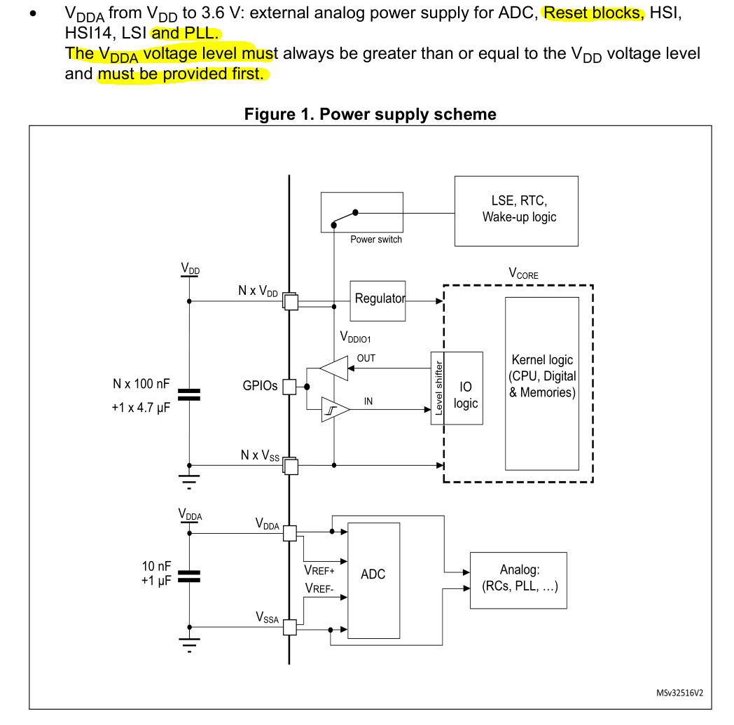
STM32 require all Power supplies (digital and analogue + VBat) to be connected and having the decoupling capacitors. If you did noy connect it the chip will not work correctly.

PCB has left the VDDA floating howvere, would that have anything to do with this since PB0 is an ADC channels?

Do not make such a assumptions - read the uC documentation. enter image description here

\$\endgroup\$

Your Answer

By clicking “Post Your Answer”, you agree to our terms of service and acknowledge you have read our privacy policy.

Not the answer you're looking for? Browse other questions tagged or ask your own question.