1
\$\begingroup\$

I have a voltage divisor to measure the voltage of my battery which serves as a battery level detector and it is connected to a GPIO pin in a microcontroller which does not have an ADC. Is it possible to obtain the analog value? And if not is there another way to obtain the value without an ADC?

I have seen a way that will compare the voltage of the Vref of my microcontroller. Is it possible this way?

For the MCU, im using a STM32WB55CGU6 and the pin used is the PB6 (pin 46)

\$\endgroup\$
8
  • \$\begingroup\$ Do you have a capacitor on that MCU pin, or can you add one? \$\endgroup\$
    – Justme
    Commented Jun 6, 2020 at 18:38
  • \$\begingroup\$ @Justme yes i can add one. Ive seen people adding a RC circuit but I dont see how that will help in the pin \$\endgroup\$
    – jellybean
    Commented Jun 6, 2020 at 18:47
  • 5
    \$\begingroup\$ If it does not need to be that precise, or this is a one-off project so you can calibrate it, would the following work: make sure battery voltage is above logic 1 threshold. After the voltage divider, put capacitor to the MCU pin. Set pin to output low. Wait for capacitor discharge. Set pin to input. Wait in a loop, counting, how long it takes for the capacitor to charge to logic 1. Counter gives a time reading you can convert to voltage. \$\endgroup\$
    – Justme
    Commented Jun 6, 2020 at 18:53
  • 2
    \$\begingroup\$ @justme Sounds like an answer. But is metastability an issue with that method? \$\endgroup\$
    – DKNguyen
    Commented Jun 6, 2020 at 19:01
  • \$\begingroup\$ What MCU do you use? \$\endgroup\$
    – dirac16
    Commented Jun 6, 2020 at 19:25

4 Answers 4

2
\$\begingroup\$

Applied my comment as an answer, with improved wording.

If it does not need to be that precise, or this is a one-off project so you can calibrate it, would the following work: make sure battery voltage is above logic 1 threshold.

After the voltage divider, put capacitor from the MCU pin to GND. Set pin to output low. Wait for capacitor discharge. Set pin to input. Wait in a loop, counting, how long it takes for the capacitor to charge to logic 1. Counter gives a time reading you can convert to voltage

\$\endgroup\$
3
\$\begingroup\$

This is an interesting challenge, I have only come up with one solution, which is kinda crude, and will be computationally relatively heavy. After all, we're trying to make an ADC for a non-ADC MCU. So this is more like proof of concept that you CAN estimate voltage without ADC:
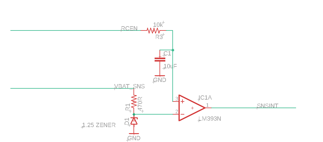
enter image description here

How I imagine this little thing should work:

  1. VBAT_SNS is just your battery voltage. It could be fed directly from the battery or, better, via P-Ch. MOSFET, that you open when you want to measure battery. If MCU is fed directly from the battery, it can be just a GPIO OUTPUT HIGH. It feeds reference 1.25V (as an example). Make sure to find the right zener and and resistor for it to have stable voltage. Or just get a voltage reference as a chip in SOT-23.
  2. RCEN will be initially GPIO OUTPUT LOW. When you want to measure voltage, you OUTPUT HIGH it (or connect to battery voltage via opening p-channel mosfet), You start charging the cap via resistor. At some point the voltage on cap is greater than reference, comparator goes HIGH. You measure the time it took to exceed 1.25V (between RCEN output HIGH and SNSINT HIGH). Now you can use formula:
Vc = V-(V*exp(-t/(R*C)))
Vc = Reference voltage (Zener's)
V = VBAT
t = time between RCEN HIGH and SNSINT HIGH
R = R3 resistance
C = C1 capacitance

Took formula from HERE
So you know all but one value - V. Honestly, this is so computationally heavy, I wouldn't want to implement in an MCU.

Poor little MCU don't want anything to do with exponents. Can you do it? Well, yeah. At least estimate. Should you do it? No.

Note: there will be some input current in the comparator, you might want to keep the resistor of RCEN relatively low not to care about it, but then get some larger cap. Better ceramic, they have less leakage current, will give cleaner results, if this is applicable in this case.

Anyway, this problem feels more like fun puzzle to invent a neat circuit rather than practical thing. From practical point of view, I seriously doubt it's worth implementing for any reason other than "look what I can do"

\$\endgroup\$
3
  • 2
    \$\begingroup\$ As a little simplification: you may simply have some saved table that will say something like: 20-22ms - 3V, 18-20ms - 3.2V, 16-18ms - 3.4V. Or whatever the real times are going to be, just try with different voltages and write down the times. if you don't need superhigh precision, but like 0%, 10%, 20%...90%,100%, this will actually work like charm \$\endgroup\$
    – Ilya
    Commented Jun 6, 2020 at 21:28
  • \$\begingroup\$ if you have a timer/counter than can be used to witch the comparitor reasonably high timing precision can be got at low cost. \$\endgroup\$ Commented Jun 7, 2020 at 1:45
  • \$\begingroup\$ What you've made here actually is an ADC. \$\endgroup\$
    – Hearth
    Commented Jun 8, 2020 at 18:56
1
\$\begingroup\$

You can use a comparator (a one-bit ADC) with a voltage reference. You can run the voltage reference through a potentiometer divider to adjust the threshold.

If you need to read more than just one value then you can use a through a digitally controlled potentiometer and basically change the reference value going to the comparator until it the output switches.

Or a voltage to frequency converter.

Or get super fancy with a sigma delta modulator but then you need to use a sigma delta demodulator in your MCU, or code one which is probably not feasible (it's a lot of processing power).

But if you want no circuitry changes, then no you cannot.

\$\endgroup\$
9
  • \$\begingroup\$ in that case for the programmation of the microcontroller? Would it be able obtain the analog value? Please let me know if its not clear as im not sure if this is the correct phrase for it \$\endgroup\$
    – jellybean
    Commented Jun 6, 2020 at 18:48
  • \$\begingroup\$ @jellybean It is not clear what you are trying to say. Are you trying to ask if you can read an analog value with no circuitry changes with only code changes? If so, the answer is no. \$\endgroup\$
    – DKNguyen
    Commented Jun 6, 2020 at 18:49
  • \$\begingroup\$ if I do add a convertor. Would the programmation of that pin change? and directl be able to receive analog values? \$\endgroup\$
    – jellybean
    Commented Jun 6, 2020 at 18:51
  • \$\begingroup\$ @jellybean When you say "converter" do you mean the voltage to frequency converter? Or the Analog to Digital Converter (ADC)? \$\endgroup\$
    – DKNguyen
    Commented Jun 6, 2020 at 18:52
  • \$\begingroup\$ for both. Im trying to see what my options are without changing too much my circuit \$\endgroup\$
    – jellybean
    Commented Jun 6, 2020 at 18:53
1
\$\begingroup\$

As a variation of the above answers. Generate a full scale triangle wave at a fixed frequency. Feed that into a comparator to the battery voltage (scaled in kind to the triangle wave). Observe the time that the comparator output is high. This time divided by the period of the triangle wave should be proportional to the battery voltage.

\$\endgroup\$

Your Answer

By clicking “Post Your Answer”, you agree to our terms of service and acknowledge you have read our privacy policy.

Not the answer you're looking for? Browse other questions tagged or ask your own question.