3
\$\begingroup\$

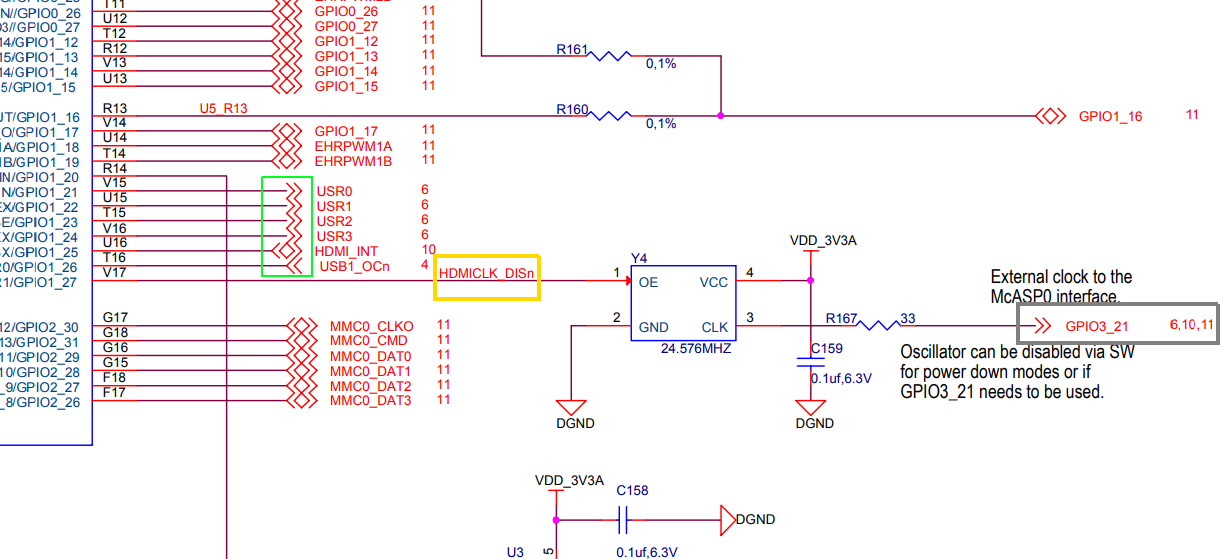
I have a schematic of an electronic circuit board or PCB. I want to know the meaning of certain symbols and labels in the diagram. I have highlighted the diagram below with green, yellow and grey coloured boxes.

enter image description here

Question 1: What is the meaning of symbols, >> , < <> > and << ?. See green box.

Question 2: What is the meaning of n in HDMICLK_DISn? See yellow box.

Question 3: What is the meaning of 6, 10, 11 in grey box?

Question 4: Why the resistors have values as zero at certain places? What does it signify? For example see the 2 resistors on top of the schematic. They have value 0.

I would appreciate answer(s) to any/some/all of above questions.

\$\endgroup\$
4
  • 1
    \$\begingroup\$ R160 and R161 appear to have a tolerance of +/- 0.1%, but no value is given. \$\endgroup\$ Commented Jun 25, 2020 at 15:49
  • \$\begingroup\$ @PeterBennett . Its a comma (,) between 0 and 1. Tolerance is 1% and value is 0. :) Thanks !! \$\endgroup\$ Commented Jun 25, 2020 at 22:14
  • 1
    \$\begingroup\$ Whoever drew this probably should've used slightly smaller >>s because now they're just merging together into one trippy pattern. \$\endgroup\$ Commented Jun 26, 2020 at 14:07
  • \$\begingroup\$ The title of the article and the questions and answers are in conflict. The symbols in question are for a schematic, not a PCB. \$\endgroup\$ Commented Jun 26, 2020 at 16:53

3 Answers 3

10
\$\begingroup\$

>> , < <> > and <<: These are called "off-page connectors". >> means that the signal originates from this page (it's an output from this page) and goes to another page. The numbers "6,10,11" are the pages that this signal goes to. On those pages you'll find those signals next to the << symbol. This symbol means that that signal originates from a different page and enters this page (its an input to this page). <<>> means this signal is a bidirectional signal. The signal can originate from this page or the other page it is present on.

The n in HDMICLK_DISn typically denotes an active low signal. I dont know about HDMI's specs but from the signal name I assume it has a clock (CLK = clock). Some name + _dis (HDMICLK_DIS) typically means that this signal's purpose to to disable some function, in this case the clock signal for HDMI, make this signal high and the clock will be disabled. Now add the "n" to then end (HDMICLK_DISn) and again it's an active low signal. A high signal on this line will keep the HDMICLK enabled but now a low signal (typically GND) will disable the HDMICLK

\$\endgroup\$
7
  • \$\begingroup\$ Thanks a lot. A small extra question please. Why is the resistors have values as zero at certain places? What does it signify? For example see the 2 resistors on top of the schematic. They have value 0. \$\endgroup\$ Commented Jun 25, 2020 at 6:18
  • 3
    \$\begingroup\$ No problem! 0 ohm resistors are used to make your circuit more flexible functionally. For example lets look at this one: GPIO1_16 enters the page and goes through those two 0 ohm resistors and enters two GPIO pins. That may fulfill my purpose but I might want this signal to only go to one of those pins in the future. I can put these two zero ohm resistors inline with the signal which allows me to take one out in the future and cut off the signal to the other pin. This is very useful when you're designing something say "I want this now, but I might want that later" \$\endgroup\$
    – Michael
    Commented Jun 25, 2020 at 6:28
  • 1
    \$\begingroup\$ (This is useful because you if you change the circuit board wiring, you need a whole new circuit board, but it's a lot easier to just take one component off a circuit board) \$\endgroup\$ Commented Jun 25, 2020 at 13:45
  • 2
    \$\begingroup\$ Given that an active-low disable signal is generally equivalent to an active-high enable signal, it would IMHO be clearer if this signal were called HDMICLK_EN. Given that this signal goes to the (active-high) Output Enable input of a clock generator chip, this would keeps things consistent. \$\endgroup\$ Commented Jun 25, 2020 at 15:39
  • \$\begingroup\$ Zero ohm resistors are used to isolate grounds in analog/digital power planes, to increase stability and precision in the analog part-evading the conmutation noises from digital sources- and ensure digital robustness-avoid the analog noises- in the digital plane \$\endgroup\$ Commented Jun 25, 2020 at 16:31
2
\$\begingroup\$

I cannot answer Q2 and Q3 without seeing the full schematic.

Answer-1: >>, << and << >> indicate the signal direction. For example, in your schematic, USR0...USR3 are outputs, and USB1_OCn is input, and GPIOs are bidirectional (i.e. can be either input or output - most likely they are left for the user's choice).

\$\endgroup\$
1
\$\begingroup\$

Zero ohm resistors are also used for hardware configuration. When connected between a GPIOpin and GND with the GPIO pin pulled high by a suitable resistor. 2 x GPIO pins gives 4 different configuration options. (00 01 10 11).

\$\endgroup\$

Your Answer

By clicking “Post Your Answer”, you agree to our terms of service and acknowledge you have read our privacy policy.

Not the answer you're looking for? Browse other questions tagged or ask your own question.