1
\$\begingroup\$

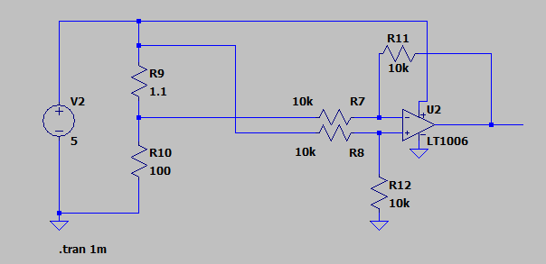
I'm trying to build a high-side current sensing circuit with a differential op-amp which can be seen below:

enter image description here

The LT1006 is actually an LM358 IRL(I know it's a peanut op-amp, but it's what I have available). Anyways, according to this setup, I should have unity gain. 5V/101.1 OHM = 49.4mA. So the shunt has 49.4mA * 1.1 OHM = 54mV across it, and therefore the LM358 should output around the same voltage, but it doesn't. I've made sure the resistors are very matched and also tried using 100k resistors. I've also experimented with different power rail voltages and even tried setups that would give a gain of 5, 10, and 20, and I still can't get the op-amp to output the expected voltage. What am I doing wrong? I've read the datasheet and I'm pretty sure I am within spec of the common mode input range.

Thanks.

\$\endgroup\$
2
  • 1
    \$\begingroup\$ The input common mode range does not extend to the positive power rail. From the schematic it is probably to the positive rail - 1.5V \$\endgroup\$ Commented Jun 27, 2020 at 15:08
  • \$\begingroup\$ @PeterSmith Yes, I believe the datasheet says VCC-1.5 or VCC-2. But am I not below that on the input? When I probe the non-inverting and inverting inputs, I fall well below the specified range. \$\endgroup\$
    – jm567
    Commented Jun 27, 2020 at 15:12

1 Answer 1

3
\$\begingroup\$

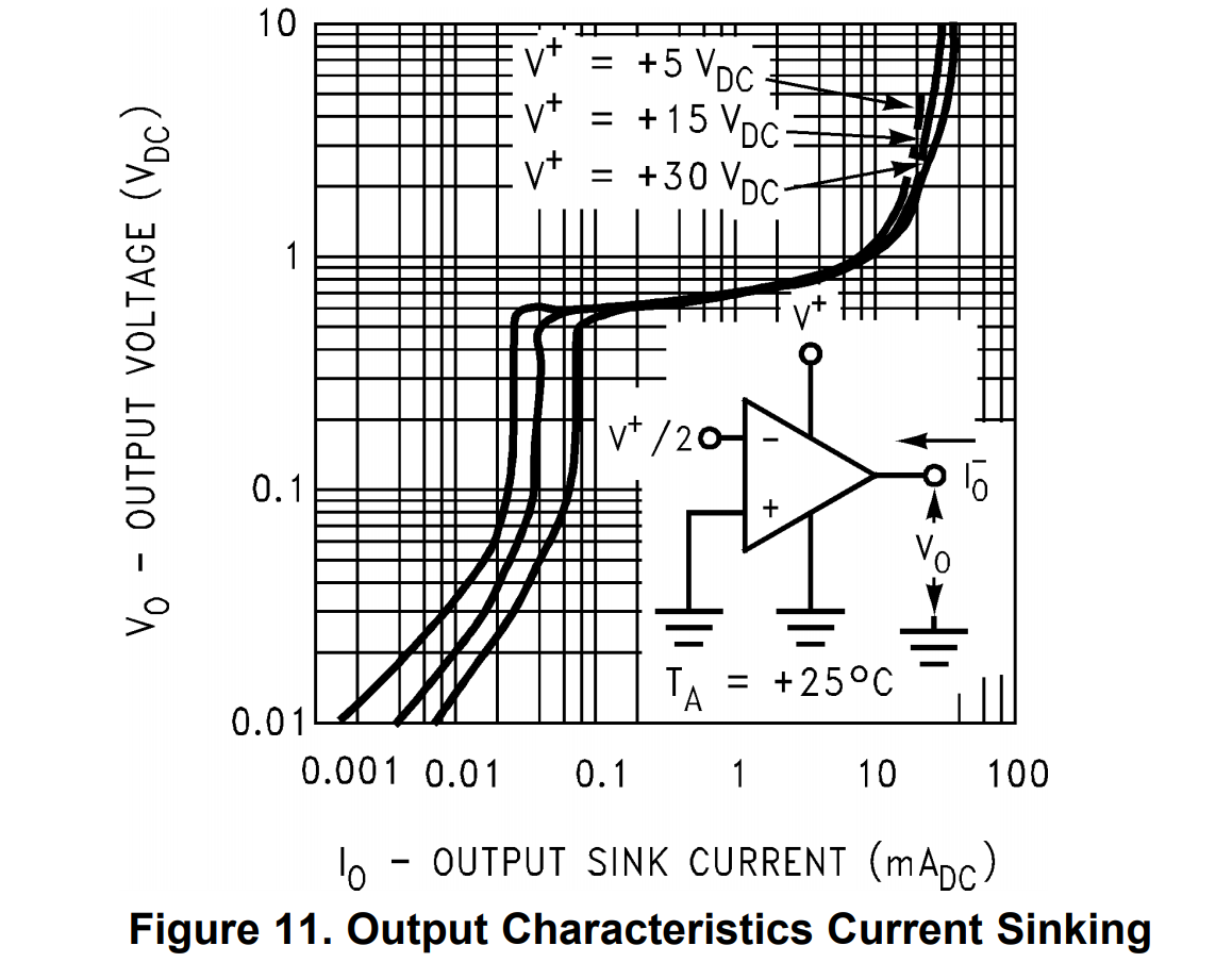
The LM358 can can't really get down to the negative rail while sinking current, and your circuit has about 250uA flowing into the output.

Increasing the resistors to 100K probably helped quite a bit, but it still is limited.

Referring to the datasheet for the typical characteristics:

enter image description here

To get down to 50mV it can typically sink perhaps 15uA with a 5V supply @ 25°C, so maybe you can count on 5-10uA in realistic conditions. And that's just to barely get down to 50mV out.


To get something useful out of this, you can increase the gain significantly so the minimum output is (preferably) in the +1V range. But then you'll run into common mode range issues if you just increase R11/R12.

\$\endgroup\$
4
  • \$\begingroup\$ Thank you. It was incredibly helpful seeing this graph. It looks like I will have to consider a rail-to-rail op-amp or a current sense amplifier. \$\endgroup\$
    – jm567
    Commented Jun 27, 2020 at 17:25
  • 1
    \$\begingroup\$ Current sense amplifier is probably the right way to go since it gets rid of the need for highly matched resistors. You can still use the LM358 as a buffer. ;-) \$\endgroup\$ Commented Jun 27, 2020 at 17:26
  • \$\begingroup\$ @SpehroPefhany It seems [tm] that adding a "pedestal" of 0.6V or so to the bottom of R12 would largely fix the issue. Yes? In a design where cost is crucial but spare ADC inputs exist then using eg a diode below R12 and measuring V_r12_lower and Vout would give "moderate accuracy" Yes 2 ? \$\endgroup\$
    – Russell McMahon
    Commented Mar 19 at 3:42
  • \$\begingroup\$ @RussellMcMahon Seems reasonable on both counts. Low side sensing in those inexpensive V/A meters uses an LM358 with some offset added, which is digitally subtracted. \$\endgroup\$ Commented Mar 19 at 6:37

Your Answer

By clicking “Post Your Answer”, you agree to our terms of service and acknowledge you have read our privacy policy.

Not the answer you're looking for? Browse other questions tagged or ask your own question.