0
\$\begingroup\$

Transimpedance-Amp

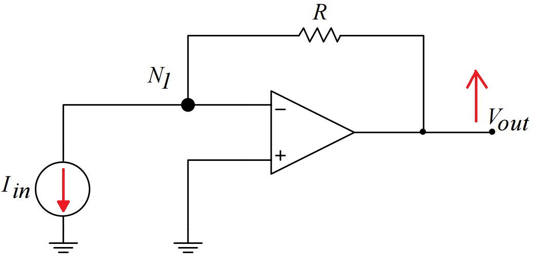
I implemented this circuit with a feedback resistance of 330 kilo ohms and a photodiode, which detects wavelengths in the infrared range.

I used the LM358 to amplify the photocurrent into voltage gain. I am using an Arduino board to read the voltage. I simply read the analog signal at the output of the amplifier.

The Arduino does not give a proper reading however. I am specutlating, that the problem is either with properly connecting to a common ground, or a damage to the amplifier.

I used a different circuit before, and it gave a reasonable sensitivity to multiple degrees of intensity. The problem however was the range of the photodiode. It is supposed to be from 0 to 1024, since the ADC in the Arduino is 10 bits. With this circuit however,it provided a range from 0 to 340 only.

So in summary with this shown circuit, how do I read a maximized range of measurement from 0 to 1024 properly?

Datasheet of the amplifier.

Datasheet of the photodiode.

\$\endgroup\$
2
  • \$\begingroup\$ Mmmmpf. The datasheet for that "photodiode" is clear as mud. The part is referred to at various times as a "PIN" diode and an "LED" and then it gives specifications that would apply to a phototransistor. So, what is it? Damifino. \$\endgroup\$
    – JRE
    Commented Jun 28, 2020 at 8:55
  • \$\begingroup\$ I agree, that datasheet is terrible, and you probably want to use something that has a useful datasheet. Even then, this is not an appropriate circuit to measure photocurrent. You need to bias the diode to get better sensitivity, typically in reverse. \$\endgroup\$ Commented Jun 28, 2020 at 8:59

1 Answer 1

2
\$\begingroup\$

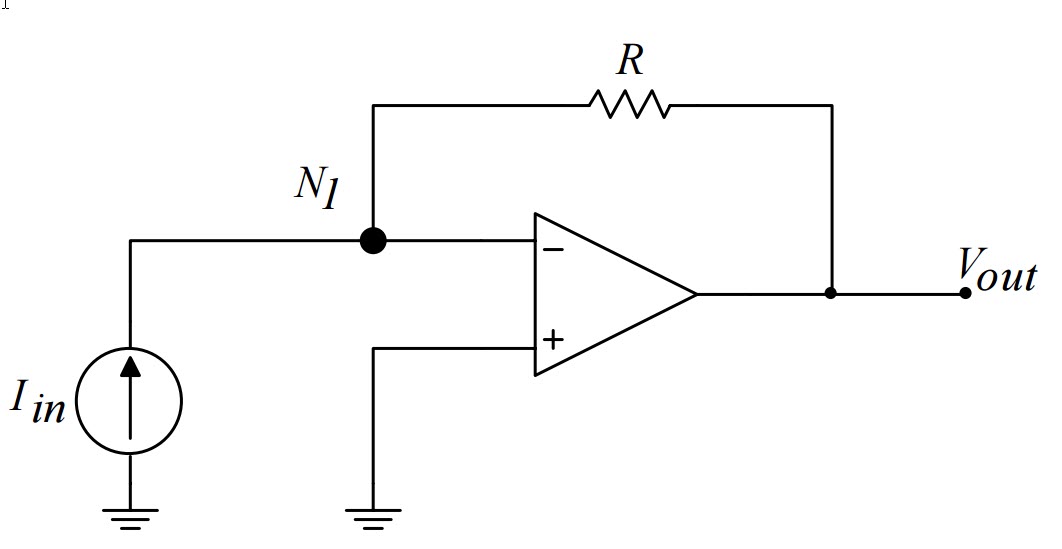
You have your photodiode upside down according to your circuit.

It should be like this: -

enter image description here

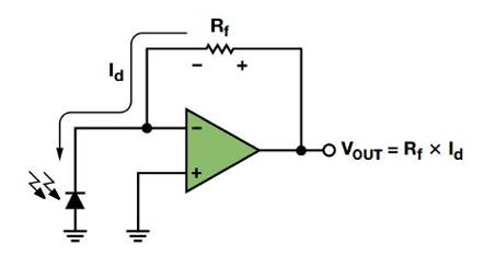
So now, with the photodiode trying to take current from the inverting input node, the output voltage of the op-amp has to rise above 0 volts to maintain that inverting input at the same potential as the non-inverting input (connected to 0 volts) and feed the right current into the photodiode. See also this: -

enter image description here

Picture taken from Photodiode Amplifier Design using Photodiode Wizard produced by Analog Devices.

See also this Q and A for possible help.

I used the LM358 to amplify the photocurrent into voltage gain

The LM358 has an input bias current of typically 50 nA and this current through the 330 kohm feedback resistor will produce an error voltage of 16.5 mV at the output. Bias currents (for BJT based op-amps) can vary a bit with temperature and also the maximum could be as high as 250 nA. If you chose a FET based op-amp you will instantly get bias currents that are a fraction of those needed by BJT based op-amps but, their bias current doubles every 10 degC rise. Something to consider.

So be aware that the LM358 isn't going to be a very good op-amp choice if you need accuracy.

\$\endgroup\$
1
  • \$\begingroup\$ +1 for revealing a major difference between FET and BJT based op amps. \$\endgroup\$
    – Carl
    Commented Jul 23, 2022 at 15:11

Your Answer

By clicking “Post Your Answer”, you agree to our terms of service and acknowledge you have read our privacy policy.

Not the answer you're looking for? Browse other questions tagged or ask your own question.