2
\$\begingroup\$

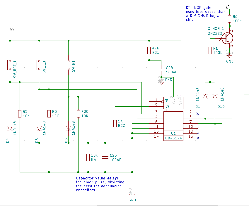
Here's a circuit which implements a radio button arrangement.

enter image description here

All switches activate the clock.

One of the switches enables a latch which has no output connection.

The other two switches each enable an output.

If neither of those outputs are enabled a DTL NOR gate creates a logic high indicating that neither switch if 'on'.

So switch one and two operate as radio buttons (mutually exclusive) and the reset switch disables the other two outputs.

If sw1 is active, and I push the button again nothing happens, sw1 remains active. I can only disable sw1 and sw2 by pressing the reset switch.

I don't want this.

It occurs to me that the reset switch COULD be made redundant. What I really need is for each switch to toggle itself on and off, and IF it toggles high to disable the other switch.

ie. (truth table)
S1 S2 S1_CURR S2_CURR S1_NEW S2_NEW
1  0  0       0       1      0
1  0  1       0       0      0
0  1  0       0       0      1
0  1  0       1       0      0
1  0  0       1       1      0
0  1  1       0       0      1
etc.

KEY
S? = status of switch 1 (1 = closed, 0 = open)
S?_CURR = status of current latch output for the given switch (1=high, 0=low)
S?_NEW = the result of the switch press

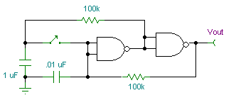
I could have one of these on each button :

enter image description here

But how would I link two of these together in a radio button arrangement (mutually exclusive).

I considered some sort of XOR arrangement but that has issues.

I think this may be a pretty standard requirement that someone might know the solution to?

Many thanks for anyone who can be bothered to read this!

\$\endgroup\$
2
  • \$\begingroup\$ what's a "radio button arrangement?" \$\endgroup\$ Commented Jun 28, 2020 at 17:20
  • \$\begingroup\$ A radio button circuit has a group of (usually SPST) momentary pushbuttons, each with a latched output. Pressing any button sets its output and clears all other outputs. The name comes from the mechanical pushbutton station selector mechanism in a car radio. \$\endgroup\$
    – AnalogKid
    Commented Jun 28, 2020 at 18:00

2 Answers 2

2
\$\begingroup\$

The alternate-action function is not a part of a standard radio button circuit.

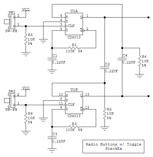
If there are only two active buttons, then this can be done with a dual D flipflop, such as a CD4013. Each half is connected as a toggle ff, and each section's Q output is differentiated into the other section's Reset input.

EDIT: First pass at a schematic. R1-C1 debounces the switch input while keeping a fast signal edge at the clock input. R2-C2 differentiates the Q output, and pulses the other circuit's Reset input when the Q output goes high. You can adjust the component values for your switch behavior, inventory, etc.

Credit to Crutschow at AAC for the switch debounce trick.

enter image description here

Expanded explanation:

As you noted in your question, you need one toggle flipflop for each switch, plus something to manage the resetting of the other circuits. The circuit I posted is pretty simple, but that is partly because it works for only two switches. Expanding this circuit for more switches gets messy very quickly.

Connecting the inverting output of a D flipflop back to its D input creates a toggle flipflop, and a 4013 has two of them, so that is the basis for the circuit. Without any of the cross-connection between the two circuits, you have two basic toggle circuits.

Switches bounce; that is, switch contacts do not come together cleanly. They bounce off of each other and then come together again under the spring force. When you press the button, the clock input can see dozens of signal edges in a few milliseconds. Without treatment, this is a good random number generator. R1-C1 is a lowpass filter that prevents the D input from changing as fast as the clock input is bouncing. The first positive edge clocks the current Q- value into the ff. this causes Q- to change to the other state, but the D input does not track this for about 16 milliseconds, approx 0.7 x the R-C time constant. If the switch contacts still are bouncing after that time you will get sporadic circuit action; increase R1 or C1 to get a longer debounce period.

On ever other switch press, the Q output will go high. C2-R2 form a highpass filter that functions as a differentiator. When Q jumps from 0 v to Vcc (-ish), that high level appears immediately at pin 10, the Reset input of the other circuit, resetting U1B immediately. Q will stay high until the next button press, and so will the end of C2 connected directly to it. But R2 starts to charge up C2 by pulling the other end down to GND. After (0.7 x R2 x C2) seconds, the voltage at pin 10 drops below the input transition level, releasing the Reset input so the circuit can accept inputs from SW2. The reset pulse width is approx. 1.6 ms.

Note: Missing from the sch is a decoupling capacitor for the chip. Use another 0.22 uF cap connected directly to pins 7 and 14.

\$\endgroup\$
6
  • \$\begingroup\$ that sounds like a solution... I'll give it a shot. \$\endgroup\$
    – Richard
    Commented Jun 28, 2020 at 20:44
  • \$\begingroup\$ Thank you.. I've tested this in LTSpice and it's perfect. I confess to not understanding quite how it works mind you. \$\endgroup\$
    – Richard
    Commented Jun 29, 2020 at 0:43
  • \$\begingroup\$ I added an expanded circuit explanation. \$\endgroup\$
    – AnalogKid
    Commented Jun 29, 2020 at 3:12
  • \$\begingroup\$ You've gone above and beyond. I would award you some bounty for this but I don't know how. The eventual PCB has a lot of power smoothing, and the chip will have a tantalum cap. This is great for me, it frees up a lot of space because the switches are momentary foot switches flush mounted on the PCB, and have a HUGE courtyard. Loosing a whole switch means I can comfortably fit everything on without using the reverse side of the board, which obviously saves me money too. \$\endgroup\$
    – Richard
    Commented Jun 29, 2020 at 12:19
  • \$\begingroup\$ Glad it works for you. NOTE: The alternate-action function above and a separate reset switch like you started with are not the same thing. The circuit above goes to a "reset" state (no outputs high) only if you hit the correct switch when one output is high. A true reset switch clears all outputs without knowing which one is high. \$\endgroup\$
    – AnalogKid
    Commented Jun 29, 2020 at 13:00
0
\$\begingroup\$

I think this may be a pretty standard requirement that someone might know the solution to?

I don't know whether this specific problem is "pretty standard" (sounds super specific to me), but the general class of problem is very common:

Each of \$N\$ buttons activate a different state. Only one state can be active.

Congratulation, that's a state machine, the most fundamental building block of digital logic!

Especially for \$N>2\$, you'd practically always implement that with the cheapest microcontroller you can find.

That's typically cheaper than buying enough logic gates to implement a Moore Machine or a Mealy Machine. And, nobody needs to reason about why some complex arangement of logic gates doesn't work as planned, if they can instead write 5 lines of code to define the state machine in software.

Your profile doesn't indicate at all whether you've programmed before, but don't be afraid: Software isn't hard, and a microcontroller really needs little effort to make it run. "Blue Pill" / Android might be a good platform to get you started.

\$\endgroup\$

Your Answer

By clicking “Post Your Answer”, you agree to our terms of service and acknowledge you have read our privacy policy.

Not the answer you're looking for? Browse other questions tagged or ask your own question.