1
\$\begingroup\$

I'm planning to use this uC board's LCD to read the humidity and temperature sensors' outputs.

Here is the datasheet for the humidity and here is for the pressure sensor.

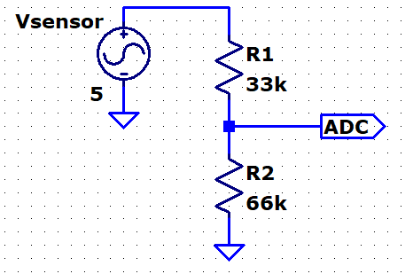
Since the ADC of the uC is 3.3V range. The sensors are max 5V output so I will use a resistor divider like such as below:

enter image description here

I will measure the precise ratio for the resistor divider above to implement in uC code.

Humidity sensor datasheet has the following figure:

enter image description here

Do I need to buffer the sensor outputs before the divider if I don't want to introduce resistor divider loading error down to 5%? I cannot find the output impedance of the sensors.

EDIT:

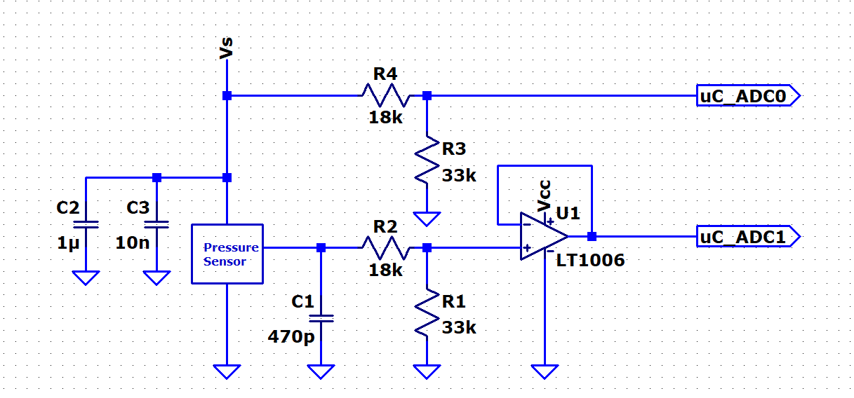
enter image description here

\$\endgroup\$

1 Answer 1

1
\$\begingroup\$

First of all, you're violating minimum load requirement. Minimum load requirement is 80kOhm, so your total resistance at the sensor output has to be below that to ensure stability. With your circuit total resistance in path to ground is 100kOhm, is too much.

Proof: here

Considering that, it looks like you can get away without buffer. Of course, you can always provide minimum load and then buffer it, it will probably be the cleanest way as long as the buffer has low noise and offsets, but I don't think it will change performance by noticable value unless you wanna go megaaccurate. Besides, there is not much info in datasheets regarding output voltage change vs output current. So you can only try it, I'm afraid. Didn't find any minimum load for pressure sensor, so I would probably buffer it and then attach or not attach minimum load resistor before buffer. That way you have a ready circuit where you can simply attach and detach load at your wish. Sensor - Buffer - Voltage divider - MCU. You either put a resistor to ground before buffer or not and see the result. Again, pick op amps carefully. Rail-to-rail, low offset voltage, bias current etc.

\$\endgroup\$
11
  • \$\begingroup\$ Thanks can this be a fine buffer analog.com/media/en/technical-documentation/data-sheets/…? It doesnt say rail to rail but says precision opmap. I have it at the momment. \$\endgroup\$
    – ty_1917
    Commented Jul 1, 2020 at 9:45
  • \$\begingroup\$ it can output in the range of 25mV - 4.0V (if no load or some hundred kiloohms). It's called output swing characteristic. It basically shows minimum and maximum output. If that's enough for your purposes, you can use it of course. By the way, don't go with superhigh resistors for voltage divider when you feed it into MCU. I didn't think about it, but MCU's input impedance is not infinite. STM32F103C8T6 blue pill MCU has input resistance of 20k only for example. So your voltage divider should be an order of magnitude smaller resistance to avoid inaccuracy. Depends on ur MCU of course. \$\endgroup\$
    – Ilya
    Commented Jul 1, 2020 at 9:55
  • \$\begingroup\$ You can always buffer voltage divider output too :) there are chips made of two op amps - perfect for two buffers \$\endgroup\$
    – Ilya
    Commented Jul 1, 2020 at 10:00
  • \$\begingroup\$ I cannot find the output impedance of the sensor. I also cannot find the input impedance of the uC's ADC. So many unknowns. So I think to buffer both after the sensor and the divider is needed as you say. But do you think LM324 suffice for such ti.com/lit/ds/symlink/…? \$\endgroup\$
    – ty_1917
    Commented Jul 1, 2020 at 10:08
  • \$\begingroup\$ output impedance of sensor is not really that relevant. Enough to say it's small. Probably some 50 Ohm or less. We're going to have kiloohms anyway. MCU probably has some 20k if it's built similarly to STM32F103C8T6. But if everything is buffered, it doesn't matter. If your op amp has 5V supply voltage, it should MOSTLY to be enough. \$\endgroup\$
    – Ilya
    Commented Jul 1, 2020 at 10:13

Your Answer

By clicking “Post Your Answer”, you agree to our terms of service and acknowledge you have read our privacy policy.

Not the answer you're looking for? Browse other questions tagged or ask your own question.