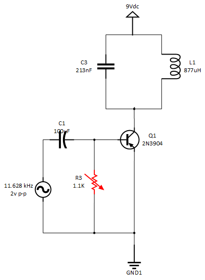
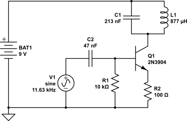
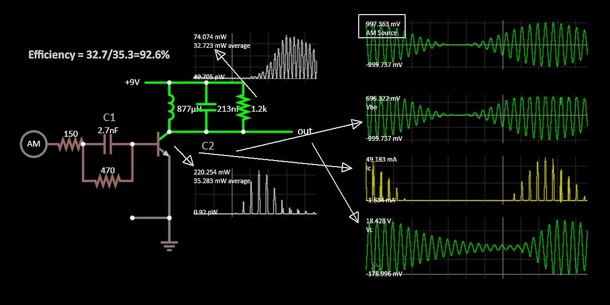
I've built a Class C amplifier for educational purposes and believe I understand the major concepts on how it works. The only piece I'm struggling with is how to calculate for the base resistor. From the resources I can find, they authors talk about calculating the RC base network for 10 times the input signal time. My experience is quite different.
The circuit below has the following: Input signal: 11.628 kHz (tuned to the tank circuit) @ 2v p-p Tank circuit: C3 = 213nf, L1 = 877mH Base clamping circuit: C1 = 100uf R = is a variable resistor. I've dialed it to 1.1K ohms, which produces the optimal output p-p signal. The circuit works as expected, but just lost on getting the right math.
My question is: what is the formula to correctly choose the base resistor? Any good resources on negative clamping circuit calculations?


