1
\$\begingroup\$

I have a high current low voltage MOSFET I'd like to drive with a higher voltage and a micro to reduce power losses through it. I built this circuit based off the typical level shifting designs. The MOSFET does not turn off. The circuit has been reconstructed twice, and both times the MOSFET works fine before and after, so I don't think I'm breaking anything. Any ideas as to why its not working?
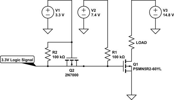
schematic

simulate this circuit – Schematic created using CircuitLab

I am a bit new to circuits, so please correct me if I've made some very silly mistake.

edit: source and drain of the 2N7000 should not be connected together like they are in the picture, not sure what happened there - source should connect to the logic signal, drain should connect to the power mosfet

\$\endgroup\$
11
  • \$\begingroup\$ What steps did you do to debug? Did you check the various nodes by using oscilloscope? If yes, could you post them here \$\endgroup\$
    – DivB
    Commented Jul 9, 2020 at 18:31
  • \$\begingroup\$ Any reason you don't want to have the micro drive the gate of Q2, and use it like an external open-drain inverter? \$\endgroup\$
    – The Photon
    Commented Jul 9, 2020 at 18:35
  • \$\begingroup\$ @ThePhoton That would invert the signal, OP might need this polarity \$\endgroup\$ Commented Jul 9, 2020 at 18:42
  • \$\begingroup\$ @CristobolPolychronopolis, if the signal comes from a micro, it's often pretty easy to invert it in software. \$\endgroup\$
    – The Photon
    Commented Jul 9, 2020 at 18:44
  • \$\begingroup\$ @ThePhoton Sometimes you don't have the source, but I'm just guessing as to why he wanted a noninverting shifter. \$\endgroup\$ Commented Jul 9, 2020 at 18:54

3 Answers 3

1
\$\begingroup\$

What might be happening is that, during turn-off, voltage drop across 2n7000 might be bigger due to 3.3V dc source being near to 2n7000 threshold voltage(check in datasheet) when it is applied across VGS.

Edit:

Explanantion: During turn-off, the charged Q1 gate capacitor has to be discharged and the path following is through the Q2 and logic controller ground. Looking at Q2 datasheet, at VGS = 3.3V, you can get Id = 0.04A(approx, from the ID vs VDS curve). Since Q1 gate current would be discharged at 0.04A causing the turn-off process to be slow. Also the VDS Q2 would increase for cap to discharge slowly since the IdQ2 current cannot increase beyond 0.04A.

Kindly check the signal on oscilloscope at Q1 drain when applying signal. If it follows the same thing, then, we can extend the discussion.

\$\endgroup\$
5
  • \$\begingroup\$ Thanks for the response. Can you expand on what you mean by "voltage drop across the 2n7000 might be bigger"? Bigger than what? \$\endgroup\$
    – g_rizzles
    Commented Jul 10, 2020 at 0:21
  • \$\begingroup\$ One thing I wanted to ask: Is the signal being applied as PWM signal. If yes? At what frequency and duty? \$\endgroup\$
    – DivB
    Commented Jul 10, 2020 at 7:52
  • \$\begingroup\$ The signal is not a PWM signal. Its either on or off with either minutes or seconds between a change. To give you some more background, its switching a brushless motor controller module on and off in order to calibration \$\endgroup\$
    – g_rizzles
    Commented Jul 10, 2020 at 13:40
  • \$\begingroup\$ Okay. I saw the comment by you when you measured the voltages again. Gate signal at Q1 appears to be proper. Is it still not working properly then? \$\endgroup\$
    – DivB
    Commented Jul 10, 2020 at 13:45
  • \$\begingroup\$ As @CristobolPolychronopolis, pointed out in your question, try changing MOSFET, it may have gone bad.(Check if you are not exceeding the current rating and voltage rating of the device before replacing one) \$\endgroup\$
    – DivB
    Commented Jul 10, 2020 at 13:47
0
\$\begingroup\$

There is nothing inherently wrong with the circuit. It will switch very slowly (which could be hard on the output MOSFET) because of the 100K, but that also limits the current into your MCU output.

Probably your implementation is at fault. Check the pinout on the 2N7000 and the other MOSFET and the resistor values, or take a sharp photo of your circuit and provide any measurements you've made. With the input grounded directly you should see almost no voltage at Q1's gate (relative to ground) and 3.3V on the gate of Q2.

Open circuit at the input and it will stay on. It has to be actively grounded to make it shut off.

\$\endgroup\$
4
  • \$\begingroup\$ Thanks for the response. I double checked pin outs and values, and they match the schematic I provided. When you say actively grounded, do you mean that there must be some sort of biasing (not sure if thats the correct term here) on the input? \$\endgroup\$
    – g_rizzles
    Commented Jul 10, 2020 at 0:23
  • \$\begingroup\$ The input has to be actively pulled to ground, like with a transistor or a switch or a direct connection to ground. Leaving it open will not work. \$\endgroup\$ Commented Jul 10, 2020 at 0:33
  • \$\begingroup\$ Gotcha, so would a push-pull micro output qualify as actively grounded? \$\endgroup\$
    – g_rizzles
    Commented Jul 10, 2020 at 0:37
  • \$\begingroup\$ Yes, it would... \$\endgroup\$ Commented Jul 10, 2020 at 0:37
0
\$\begingroup\$

Turns out the issue was a dead power mosfet. Replaced the part and the circuit worked fine. I also replaced the 2n7000 with a lower threshold mosfet to make sure it actually switches.

\$\endgroup\$

Your Answer

By clicking “Post Your Answer”, you agree to our terms of service and acknowledge you have read our privacy policy.

Not the answer you're looking for? Browse other questions tagged or ask your own question.