0
\$\begingroup\$

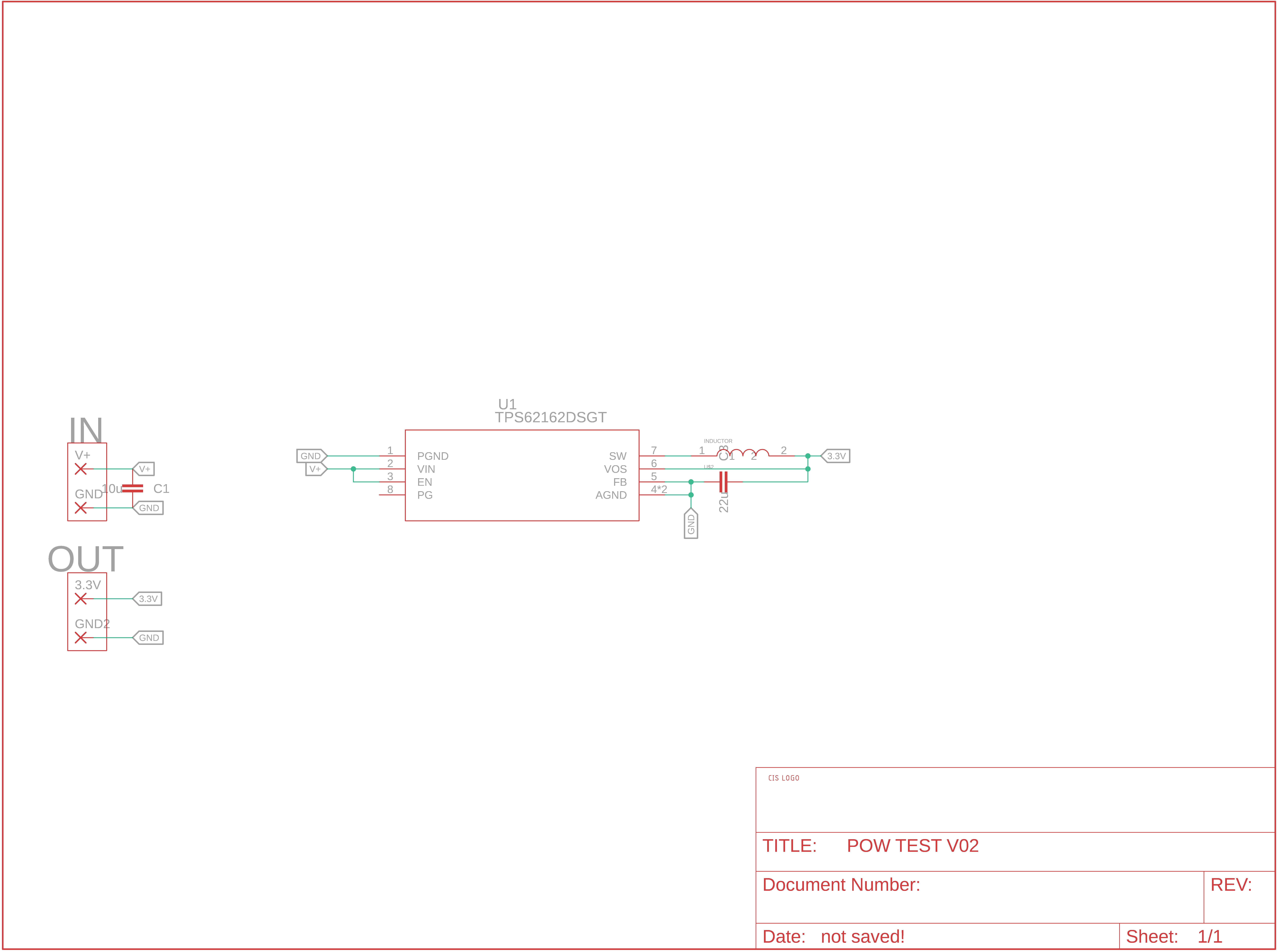
I need a 12V and 3.3V power supply for a circuit, so I designed a regulator onto a board to turn the 12V to 3.3V. I used the TI TPS62162DSGT to do this, and my schematic looks like:

Schematic of board

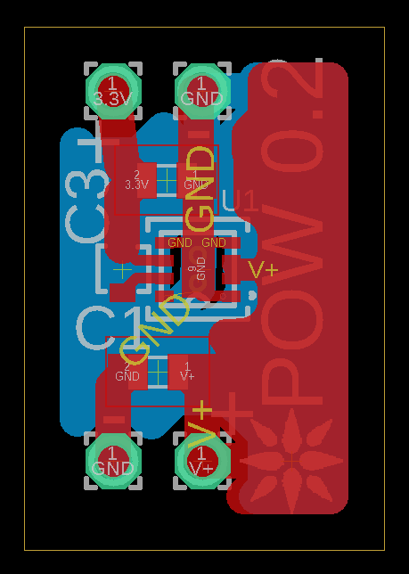
I used the inductor and capacitor BKPB001608DZ2R2MA2 and GRM188R60J226MEA0D respectively along with this small test board:

Board layout

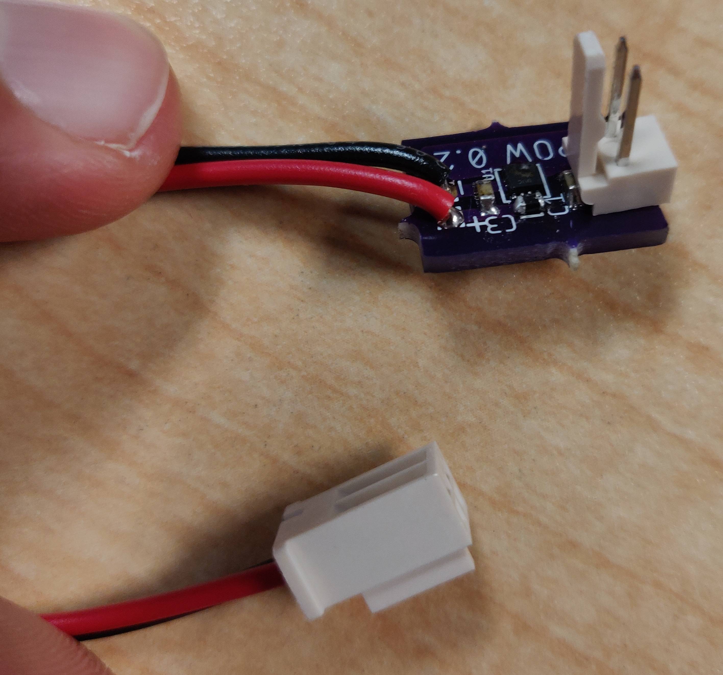
I soldered up the board using low temp solder paste and a hot plate, which is less than ideal. But I expected it'd be fine for a test. Checking the components, they seem like they are soldered correctly and in place:

Physical board

I checked all of the connections and found no shorts, and the capacitance is correct. Unfortunately my multi-meter won't measure inductance. I plugged it in, and it worked fine, although the voltage I measured was only 3.26V. I unplugged it and plugged it back in 2 more times, there was a pop, the device began heating, and the housing briefly caught fire. This has happened twice now, so I suspect a design failure on my part, but I've checked the datasheet and TI's "WEBENCH" numerous times, and can't pin it down. Maybe the ground or voltage side is making contact first, but it wasn't grounding through anything so far as I can tell (off the table). I feel like an idiot, but does anyone know what's happening, I can't figure it out. Thanks in advance.

\$\endgroup\$
17
  • 1
    \$\begingroup\$ Do you have any load connected to the 3.3V side? If so, what and how is it connected? \$\endgroup\$ Commented Jul 9, 2020 at 19:14
  • 1
    \$\begingroup\$ What is supplying your 12V power to the input? Since it sounds the failure occurs when hot plugging into the 12V, I suspect a transient overvoltage on the input due to the input supply overshooting or line inductance and bouncing contacts. Can you put a scope on the input voltage? You could solder a TVS device right across the input terminals to absorb any transient overvoltage. \$\endgroup\$
    – John D
    Commented Jul 9, 2020 at 19:45
  • 1
    \$\begingroup\$ @SillyInventor The input cap should help, but it's a ceramic 10uF which may not have much capacitance left with 12V DC bias on it. Can't tell without knowing the part number though. Also hard to say what the response of your 12V adapter is, though it does have OVP at 140% of rated voltage so it theoretically shouldn't reach 17V. \$\endgroup\$
    – John D
    Commented Jul 9, 2020 at 21:00
  • 1
    \$\begingroup\$ @Mike The OP says it regulated initially, and even if it wasn't the fixed version it shouldn't blow up with 12V applied to the input. \$\endgroup\$
    – John D
    Commented Jul 9, 2020 at 23:31
  • 1
    \$\begingroup\$ Possible scenario: The supply is not grounded. There's likely some high voltage on the DC output relative to ground when it is not connected to anything. This is due to internal capacitance to mains inside the supply. When you plug the supply in, sometimes the high voltage pops the regulator on your board. You may avoid this by either using a grounded supply, having more input capacitance, using a connector which connects ground first, then connecting 12V, incorporating a zener across the input, switching off the supply at mains rather than plugging/unplugging. \$\endgroup\$
    – elchambro
    Commented Jul 10, 2020 at 1:31

1 Answer 1

3
\$\begingroup\$

Since it sounds the failure occurs when hot plugging into the 12V, I suspect a transient overvoltage on the input due to the input supply overshooting or line inductance and bouncing contacts. You could solder a TVS device right across the input terminals to absorb any transient overvoltage.

\$\endgroup\$

Your Answer

By clicking “Post Your Answer”, you agree to our terms of service and acknowledge you have read our privacy policy.

Not the answer you're looking for? Browse other questions tagged or ask your own question.