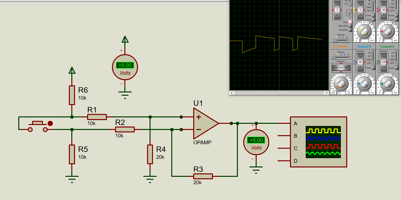
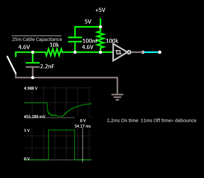
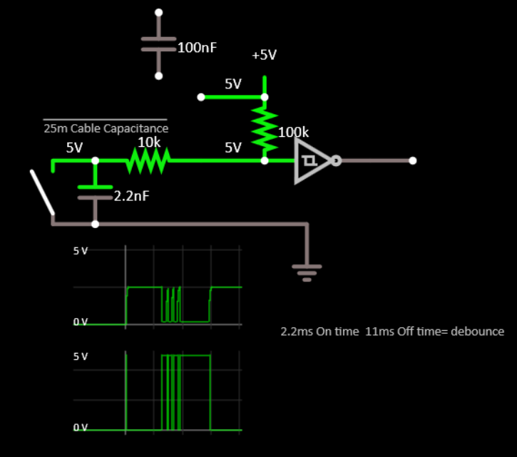
I am trying to determine if it is feasible to use an op-amp to interface a button 25 meters away. A user suggested this solution to me and im trying to explore it. He suggested to use a differential configuration to protect against common mode transients and false button presses. I tried recreating the circuit in proteus for simulation but i am getting weird results, i do not know if its proteus that is wrong or if its actually correct.
The circuit supposedly outputs 5v if a button is not pressed and 0v if the button is pressed
I am using a generic simulation model for the op amp. Notice the oscilloscope reading at the start you see a flat line at the beginning that is 0v. When a button is pressed it dips down to a - 5v but the voltmeter on the output will show 0v (not -5v like the oscilloscope). When button is released it shoots up to 2.5 volts and gradually go to 0v, but the voltmeter will read 5v, notice the leading point of the line where it is near zero but the voltmeter is at 5v?
Which one do i believe? Have i missed something? I have checked the schematic and it seems to match from other sources (example). The actual op-amp i plan to use is this.can i actually expect the proper voltages (0v and 5v) on the output of the op-amp in reality?
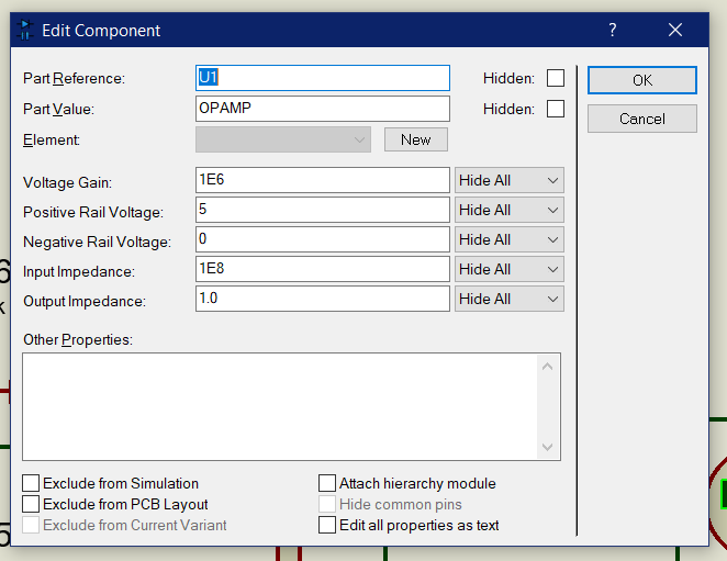
here is the op-amp property the one used above. I have actually tried using a model of an actual IC and the behaivor is the same where i am getting negative voltages on button press.


