1
\$\begingroup\$

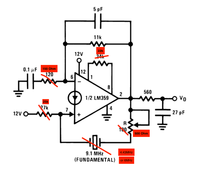
enter image description hereI'm trying to design a Crystal Oscillator based on the LM359 chip and the schematic on the datasheet but it's not working. It does not do anything.

What I'm doing wrong? I changed some components because I don't have the ones on the datasheet.

By the way, this is not the first time I'm trying to design something that's on a datasheet and doesn't work...

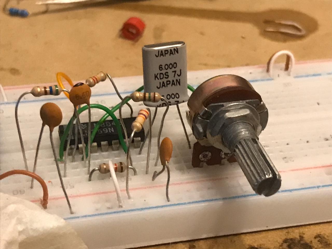
Thanks in advance! LM359 Crystal Oscillator

Picture of protoboard

\$\endgroup\$
14
  • \$\begingroup\$ What is the voltage on pin 2 with no crystal fitted? \$\endgroup\$ Commented Jul 14, 2020 at 20:21
  • \$\begingroup\$ Voltage on Pin 2 without crystal (not bridging the points where the crystal was) is between 5.2v and 5.8v \$\endgroup\$ Commented Jul 14, 2020 at 20:31
  • \$\begingroup\$ Seems like the biasing is reasonable. How good is your oscilloscope? That's a pretty HF amplifier, it might be oscillating in the VHF range. \$\endgroup\$ Commented Jul 14, 2020 at 20:34
  • \$\begingroup\$ Can you show your layout or a picture of your setup? \$\endgroup\$
    – Justin
    Commented Jul 14, 2020 at 20:42
  • 1
    \$\begingroup\$ I'm not a super-duper Norton current amplifier expert, but your part substitution looks fair. @Justin beat me to asking you to show your setup -- at those frequencies the layout matters; if it's on a protoboard with a scramble of wires you're almost guaranteed it won't work. You probably can make it work on a protoboard, but only by taking great care. You can probably screw it up on a PCB, if you're un-careful enough. \$\endgroup\$
    – TimWescott
    Commented Jul 14, 2020 at 20:45

2 Answers 2

2
\$\begingroup\$

If you are able to get this working on a proto-board, it is by accident and not design. The leakage capacitance on a proto-board is greater than some of the capacitors you are using. Proper use of de-coupling capacitors on the power supply is neigh impossible due to inductance in the proto-board conductors. Its upper limit is often < 1 MHZ.

In general, proto-boards are not good for high frequencies, high voltage, high current or high impedance. For a simple NE555 timer to make an LED flash, they work ok.

If you do manage to get this working, it will likely have a noisy output.

\$\endgroup\$
2
  • \$\begingroup\$ I've had a circuit that operated at 30kHz not work on a breadboard but did on a protoboard. Not to suggest the upper limit of a breadboard is 30kHz but just supporting this answer \$\endgroup\$
    – Michael
    Commented Jul 15, 2020 at 2:17
  • \$\begingroup\$ This circuit, an RGB encoder circuit with 4.43MHz oscillation based on AD722, a video amplifier and another 16MHz crystal clock with varactor circuit tied to the XTAL's ATMEL328 are all working on two protoboards right now. I know protoboards are not built for this, but they are all working with some noise, but working really well. Even on the FB Video Circuits group some people are designing video processors and generators starting on protoboards and they work. I don't want to go against your comment because I know that this is far from perfect! \$\endgroup\$ Commented Jul 15, 2020 at 17:30
1
\$\begingroup\$

Remove 5pF cap. was the solution add >= 0.01 uF on Vcc to gnd near IC and use short leads made the signal cleaner.

Everything as instructed by Tony Stewart.

\$\endgroup\$

Your Answer

By clicking “Post Your Answer”, you agree to our terms of service and acknowledge you have read our privacy policy.

Not the answer you're looking for? Browse other questions tagged or ask your own question.