0
\$\begingroup\$

In my Arduino 3.3V project I have a problem shutting down a GPS module.

When it "sleeps" with a command, it comsumes 2mA which is way too much for my project. To my understanding I have to build a high side FET to switch the module ON/OFF.

Do I have to use a BC212B (PNP) transistor? Why is the current negative?

I read this problem for a high side switch:

"In that case, it'd be impossible to turn the switch off because VB (connecting to the control pin) would always be less than VE."

Since LiPo is 3.3V-4.2V and to my knowledge the pins of feather are ~3.3V this is a problem. Right? So, I do I need a MOSFET or an NPN like BC546?

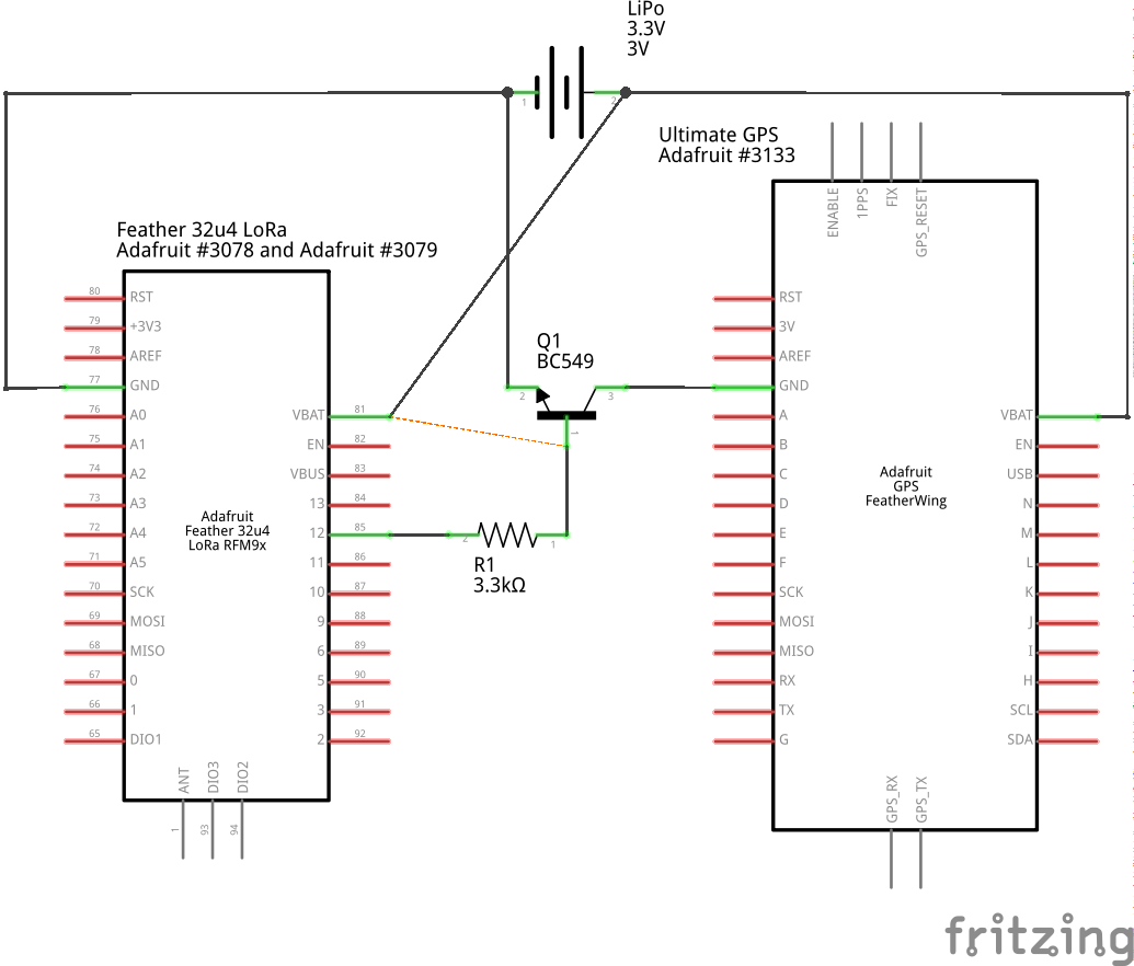
I tried two diagrams, they are right?

Low side switch (I think not recommended)

enter image description here

High side switch (recommended but unusable?)

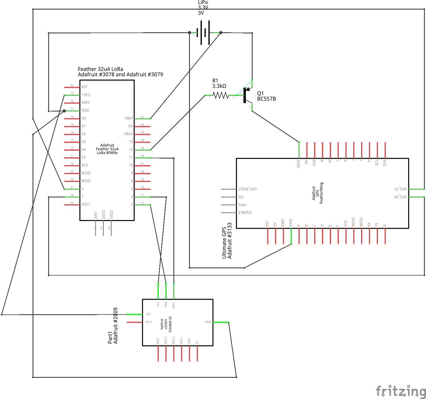
High Side Switch UPDATED with all connections

My setup Feather 32u4 (max 10mA per pin) 3.3V

GPS module needs 20-25ma (let's assume 30mA) but in the future I may need to use a more hungry module ~50mA.

I want low power level like this guy.

My idea is to feed the transistor (BC549) from lipo battery 3.3V - 4.2V and to control the transistor with an output pin of the Feather.

If I understood the basic from transistors, the more current in base, the more current in output (device). I have to supply 0.1mA to have 50mA on output of transistor (worst case: cold), right?

In BC557B PNP specs the numbers are positive.

Questions:

  1. Can I power ON/OFF my GPS module with a transistor?

  2. What resistor to base for low consumption for 30mA scenario and 50mA scenario? 3.3K (30mA) and 1.1K (50mA)?

  3. I read that I have losses with a transistor of 0.2V (or 0.6V?), so when my battery goes to 3.4 volts my module will it be problematic? I think it needs 3.3 volts not sure about 3V.

UPDATE: added all the components

\$\endgroup\$
8
  • \$\begingroup\$ Surely some GPS module pins that you've shown open circuit will be wired, including TX, RX among others? Connected pins can provide current paths that flummox your attempts at power-down, and could really mess with the GPS module internals. You really must show a complete schematic. \$\endgroup\$
    – glen_geek
    Commented Jul 19, 2020 at 18:13
  • \$\begingroup\$ Yes, TX / RX are connected to Feather (left), also a LIS3DH to I2C and Vo + GND of feather (left) \$\endgroup\$
    – krg
    Commented Jul 19, 2020 at 18:31
  • \$\begingroup\$ @glen_geek updated with all devices / connections. \$\endgroup\$
    – krg
    Commented Jul 19, 2020 at 18:51
  • \$\begingroup\$ The GPS Featherwing schematic shows a P-channel MOSfet on-board. It's gate is pulled to ground with a resistor. So the GPS is powered by default. The MOSfet's gate is accessible to pull high by your Feather 32U4 (which will de-power the GPS). Why are you not using this feature to cut power to the GPS Featherwing? \$\endgroup\$
    – glen_geek
    Commented Jul 19, 2020 at 20:30
  • \$\begingroup\$ Thank you for reading the schematic. You talk about the EN pin of GPS? I already did that but I have +2mA. For that reason I want to “cut” the line some way. I only leave a line to the battery (7μA) \$\endgroup\$
    – krg
    Commented Jul 20, 2020 at 6:38

2 Answers 2

0
\$\begingroup\$

Forget getting into 300uA sleep with this feather, Battery charger and voltage regulator chips consume in region of 1mA each while doing nothing...

Run GPS from same supply as MCU and your PNP circuit (with added pull up resistor to base) will work.

\$\endgroup\$
5
  • \$\begingroup\$ Thank you for the comment. I am at 0.3mA (300uA) with feather alone. When connecting GPS (after sleep) I am +2ma (2.6mA with LIS3DH accellerometer). I think my battery charger is broken. Maybe this is the reason. :) Battery charger consumes when no VBUS is present? \$\endgroup\$
    – krg
    Commented Jul 19, 2020 at 18:27
  • \$\begingroup\$ "Run GPS from same supply as MCU and your PNP circuit (with added pull up resistor to base) will work." This is the second schematic, right #1? I had a different idea. Run GPS not from battery but from 3Vo of Feather, so the issue of "In that case, it'd be impossible to turn the switch off because VB (connecting to the control pin) would always be less than VE." will be eliminated. Right? #2 \$\endgroup\$
    – krg
    Commented Jul 19, 2020 at 18:35
  • \$\begingroup\$ KRG you've just put my suggestion in different words.... \$\endgroup\$
    – zajc3w
    Commented Jul 19, 2020 at 18:44
  • \$\begingroup\$ thank you! "same supply" to my mind was battery, but obviously you meant after regulator. \$\endgroup\$
    – krg
    Commented Jul 19, 2020 at 18:54
  • \$\begingroup\$ Done but 3.3K resistor is wrong. Even 680R is wrong - not enough current on Emitter. It works with 330R. Need to check it for longterm. \$\endgroup\$
    – krg
    Commented Aug 4, 2020 at 8:19
0
\$\begingroup\$

Regarding the question about BJT PNP transistor as a high side on/off switch the transistor must be biased to operate in the saturation region when "on" and in the cutoff region when "off".

In each respective datasheet below look for section Collector-Emitter Saturation Voltage. Note for all three devices the ratio of collector current to base current is roughly 20. Also the highest and worst case voltage drop Vce = 0.6 volt. The base current must be enough to drive the transistor into saturation at the maximum current draw of the load so you would reduce base resistance to increase the base current as necessary. The design pattern is similar for a mosfet although gate charge turns the device on with little input current drawn and the drain-source voltage drop would replace the collector-emitter voltage for a saturated "ON" state.

https://www.onsemi.com/pub/Collateral/BC556B-D.PDF

https://www.onsemi.com/pub/Collateral/BC212B-D.PDF

https://diotec.com/tl_files/diotec/files/pdf/datasheets/bc546.pdf

\$\endgroup\$

Your Answer

By clicking “Post Your Answer”, you agree to our terms of service and acknowledge you have read our privacy policy.

Not the answer you're looking for? Browse other questions tagged or ask your own question.