1
\$\begingroup\$

I'm implementing an EC11E rotary encoder which has 3 pins + 2 pins for a switch. It seems like most of the projects I've seen online wire A/B and GND to the microcontroller, which to me, makes sense.

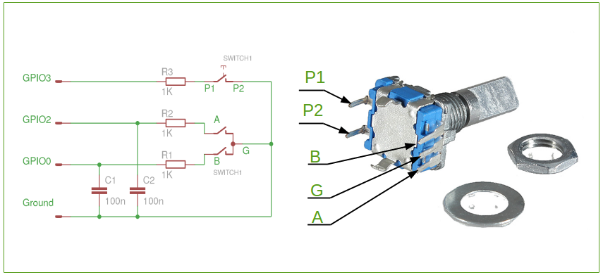
However, at the same time, I've seen a few references to schematics which include debouncing capacitors and resistors like below.

enter image description here

However, I don't understand why this is actually necessary. From what I understand, since the quadrature encoding effectively presents itself as a square wave, it shouldn't need debouncing, given the contacts either touch or don't touch.

Do I actually need these debouncing capacitors and resistors in my circuit?

As well, it seems like most breakout boards for encoders include a VCC line for pull-up. However, the MCU I'm using [AT90USB646] already includes internal pull-ups on all its GPIO pins. WIll I still need a pull up line then?

\$\endgroup\$
2
  • \$\begingroup\$ Different encoders will behave differently. Mechanical ones will vary, optical ones are usually cleaner but also may vary, too. I don't think I'd use external parts, though. I'd stick with software debouncing, if you find you need it. This is very easy to test. If you have a scope with capture, or if you have a logic analyzer that captures data, or if you write your own using your MCU. In any of these ways, you can capture very fast data from your switch and examine it. (I'd recommend finding a way of guaranteeing precision sampling, so I'd write in assembly for this if using the MCU.) \$\endgroup\$
    – jonk
    Commented Jul 24, 2020 at 4:46
  • \$\begingroup\$ After looking quickly at the datasheet, these look mechanical and not optical. They also specify the chatter and bounce on the sheet. Those are just specs, though. You should verify by measuring. A "trust but verify" approach. Then you can write us about what you observed and better suggestions can be had from that. That said, these look as though they will need debouncing. \$\endgroup\$
    – jonk
    Commented Jul 24, 2020 at 4:48

3 Answers 3

4
\$\begingroup\$

Those rotary switches are nothing more than mechanical switches. And like all mechanical switches, these will have contact bounce. The contacts either touch, or don't, and they do that many times rapidly during the transition, and due to oxidation there always a state where the contacts have a bad connection so it can be indeterminate if the signal is high or low.

Some other rotary encoder manufacturers (Bourns) clearly state a default application circuit which includes pull-up resistor, a capacitor, and a series resistor, and also include default values for them.

The pull-up resistance is selected to provide at least the minimum specified wetting current to keep the contacts clean. The series resistor will limit the current below maximum rating so that the contacts do not just short the fully charged capacitor directly. And then the capacitor is there to act as a low pass filter for the contact bounce.

The pull-up resistance must be low enough value to make sharp enough rising edges. Internal pull-ups in MCUs are quite high in value and thus can result in slow edges, especially if you have the capacitor there.

As the capacitor makes the edge rate slower, in some applications a Schmitt trigger buffer is useful to add hysteresis and square up the signal again to have sharp edges as in some applications the slow edges can be a problem.

So, the parts are not necessary, and you may not need any of these external components. The software just needs to cope with whatever garbage happens on the encoder lines, which means more complex software debouncing, dead time between detecting interrupts etc. And if the pull-ups don't provide enough current, the encoder contacts may oxidize and bounce even more over time.

\$\endgroup\$
3
\$\begingroup\$

No, you don't need them. You do need to cover the bounce period as specified in the datasheet using firmware methods (or equivalent if you are using an FPGA).

Fast (enough) sampling using a periodic ISR works well.

They do not actually debounce reliably unless you have Schmidt trigger inputs. They help with possible ESD through the metal shaft.

Personally, I like to see some series resistance on any inputs, and the internal pullups on most MCUs are a bit high resistance for my preference (for noise immunity with the switch in the open state, especially on a one or two layer board), but you can certainly use the internal pullups if you want.

\$\endgroup\$
3
\$\begingroup\$

I have been currently using a EC11 rotary encoder, which I have assembled just like described in the datasheet with no debouncing methods, and it works just fine as stated in the datasheet. No matter how fast I would switch through states, they've never bounced and it works very well. You can check that on an oscilloscope, as you move it in the clockwise direction you'll see one of the pins switching from either 0 to 1 or 1 to 0 (depending on the initial state) in \$\approx 40\,ms\$ ahead of the other. When moving counterclockwise, you'll face the same event with the moving pin order reversed though.

\$\endgroup\$

Your Answer

By clicking “Post Your Answer”, you agree to our terms of service and acknowledge you have read our privacy policy.

Not the answer you're looking for? Browse other questions tagged or ask your own question.