I have a PCB with some connectors and wanted to identify which type there are of.
How do the experts approach the problem, to identify the type?
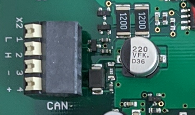
For example, the picture below shows a connector, obviously written CAN on it. So it seems easy to say, it must be a CAN Bus. The L and H could be CAN-High and CAN-Low, - maybe for Ground and + for Vcc. So it already turns into guessing.
If you look into the CAN Bus specification, maybe on automotive part, there are always much more wires than just these 4. So is it really a CAN Bus?
Another one:
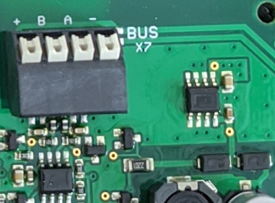
If you look closely, there is BUS written on it, so good indication for a BUS connector. When searching around the internet, BUSes which wires are sometimes labelled A or B, may lead to the idea, it maybe a RS485 Bus connector. But this is again a wild guess. Also it seems that many companies, label + and - or A and B differently, from what i read so far.
If this is really a RS485, why it has 4 wires, the only types I could find are 2 wired or 4 wired, but the 4 wired has actually 5 wires in the schematic description TD+,TD-,RD+,RD-,GND. Again confusing.
So is there an expert approach or best practice for identifying connectors or electric components in general or is this only possible by experience?


