3
\$\begingroup\$

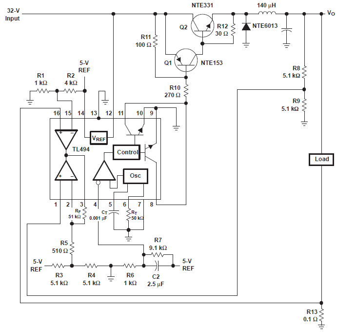
I'm designing a PWM output for a DC motor and I'm using TL494CN chip.

It got two error amplifiers and one feedback. I can't understand why there are error amplifiers and a feedback there? What does that error amplifier do in there? I can't figure out.

enter image description here

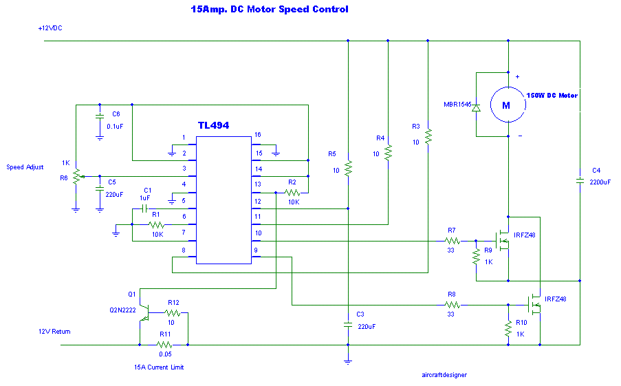
And I have reviewed some motor driver circuits, like this one enter image description here

I can't figure out why he connected reference voltage to error amplifier IN- pin?

Is that error amplifier gives a unity gain? Is that what it mean?

\$\endgroup\$

2 Answers 2

3
\$\begingroup\$

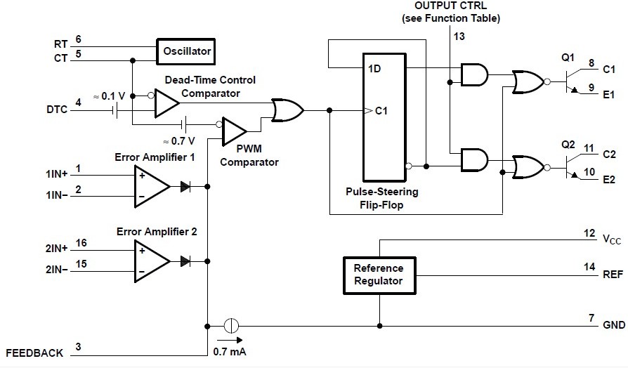
The intended use of the TL494 is a closed loop SMPS controller. Error amps are used in the feedback loop to make the output voltage regulated.

enter image description here (source: fig.35 here)

On the other hand, you are re-purposing TL494 as a PWM motor controller. You only want the PWM function without closed loop feedback. You don't need the error amps, and they shouldn't interfere. Notice that:

  • Error amps are connected to the feedback node through diodes
  • Feedback node is accessible on pin.3.

If you can have the output of the error amps always below the feedback (pin.3), then the diodes will always be reverse-biased, and the error amps will not affect the operation of TL494.

Look at the 2nd circuit in the O.P. Both error amps are wired as comparators such that V(IN+) < V(IN-) always. The output of the error amps is always low and lower than the feedback.
That is what is needed.

\$\endgroup\$
1
  • \$\begingroup\$ so you have used RF/R5 gain of error amplifier,Am I right here? \$\endgroup\$ Commented Dec 14, 2012 at 23:15
1
\$\begingroup\$

In most PWM-based power supply controllers, the purpose of the error amplifier is to generate a control voltage that is compared with a ramp voltage to determine the on-time of the PWM generator (usually a flip-flop).

One input to the amplifier (the non-inverting) is a DC reference voltage. The other input (the input) is a scaled representation of the output voltage. To stabilize the converter, some compensation is connected between the output of the amplifier and the non-inverting input. The rest of the converter is in parallel with the compensation, and the output of the error amplifier will settle at an operating point depending on the setpoint desired.

As you can imagine, if this operating point is zero (i.e. the feedback voltage is higher than the reference voltage), the duty cycle that will be generated is zero. If the feedback voltage is lower than the reference, the duty cycle will increase, which increases the feedback voltage, reduces the error, which lowers the operating point, lowers the duty cycle, etc. etc.

The motor application forces the error amplifier outputs to swing to zero (non-inverting tied high, inverting tied low), but the error amplifier output is being overridden with the potentiometer circuit. This allows one to directly program a control voltage with the potentiometer, which generates the PWM duty cycle independently of the error amplifiers and with no feedback.
\$\endgroup\$

Your Answer

By clicking “Post Your Answer”, you agree to our terms of service and acknowledge you have read our privacy policy.

Not the answer you're looking for? Browse other questions tagged or ask your own question.