0
\$\begingroup\$

I need help finding the gain \$K\$ so that the phase margin for the system equals 50°.

$$F(s) = K$$

$$G(s) = \dfrac{1}{(s+1)^2}$$

\$v\$ is a process disturbance sinusoid with amplitude 2.5 and freqency 0.5 rad/s. Image below.

Closed Loop Transfer Function

Now I need to find K so that the phase margin = 50°. I tried:

\$\varphi_m = 180^\circ\$ \$+ \arg G(i\omega_c) + \arg F(i\omega_c) = 50^\circ\$

and solve for \$\omega_c\$ but I can't really figure out how to. Do I have to account for the disturbance as well? If so, why? If not, why not?

\$\endgroup\$
6
  • 2
    \$\begingroup\$ No - the disturbance has nothing to do with stability margins. Are you able to find the phase response for G(s)? \$\endgroup\$
    – LvW
    Commented Aug 19, 2020 at 9:32
  • \$\begingroup\$ @LvW I got: arg G(jw) = arctan(0) - arctan(2w/(1-w)) = -arctan(2w/(1-w)). I know that arg F + arg G = 50-180 deg. \$\endgroup\$
    – mati
    Commented Aug 19, 2020 at 11:33
  • 1
    \$\begingroup\$ PM only depends on the OLTF. Signals don't matter. \$\endgroup\$
    – Chu
    Commented Aug 19, 2020 at 12:27
  • \$\begingroup\$ This is somewhat like 2 non-inverting Op Amps with negative feedback and choose gain so PM 50deg, at what gain. Or in other words , what is the GBW? what is BW and PM with a closed loop gain of 1 and at f-3dB \$\endgroup\$
    – D.A.S.
    Commented Aug 19, 2020 at 12:29
  • \$\begingroup\$ Dont use the phase equation to find \$\omega_c\$. Use the gain equation (i.e. the definition of gain cross over frequency) to find \$omega_c\$. \$|G(\omega_c)\cdot F(\omega_c)| = 1\$. Solve for \$\omega_c\$ from this. Then use that in the phase equation to find K. \$\endgroup\$
    – AJN
    Commented Aug 19, 2020 at 14:29

3 Answers 3

1
\$\begingroup\$

From you question I understand that you have written one equation and have unknown variables in it; viz, \$\omega_c\$ and K. If you write one more equation, you may be able to solve for K. To that end,

Definition of gain cross over frequency is

\$ \begin{align} |GF|_{s=j\omega_c} ={}& 1\\ \frac{K}{|1+j\omega_c|^2} ={}& 1\\ K^2={}& (1+\omega_c^2)^2 \\ \end{align}\$

Solve for \$\omega_c\$ in terms of K.

In the phase equation you already have with you, substitute \$\omega_c\$ with the expression containing K. Now that equation has only one unknown, viz. K. Solve!

\$\endgroup\$
0
\$\begingroup\$

I don't know if the following method is the easiest technique to find k given phase margin or not.

The following equation gives phase margin when damping ratio, zeta is known. We want to know zeta given phase margin but I had trouble trying to make zeta the subject, so I used the equation as shown and entered several values for zeta until I converged on a phase margin of 50 degrees.

Equation

It didn't take long to find that a value for zeta of 0.478 gives a phase margin of 50 degrees.

Next we derive the closed loop transfer function which is:-

Transfer Function

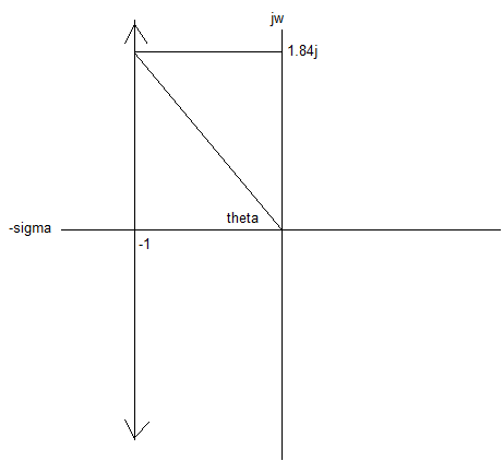
Next we look at the characteristic equation and, using the Root Locus technique, we plot the loci of the closed loop poles as k is varied from zero to infinity. The two loci start at (-1,j0) because, for k=0, we have two real and identical poles meaning that for k=0, zeta =1 and we have critical damping. As k is increased in value the poles become a pair of complex conjugate poles and move away from each other to infinity parallel to the jw axis.

The characteristic equation, which we solve for values of k from 0 to infinity, is:

Characteristic equation

The loci of the poles on the s plane look like this:
s plane

Now the damping ratio is the cosine of the angle (theta) which the vector between the origin and a particular pole position makes with the real axis. For a value for zeta of 0.478 we have theta = 61.45 degrees which, by simple trigonometry, gives a jw value of 1.8j (incidentally this is the damped natural frequency, Wd). So our pole positions, for zeta = 0.478, are (-1,+j1.8) and (-1,-j1.8).

Now, to find the value of k which gives these pole positions on the root locus we simply take the distances from the two open loop poles to the closed loop poles and multiply them together. The open loop poles are identical to the closed loop poles when k=0 that is to say the open loop pole positions are at the start of the root locus.

So, k = 1.84 * 1.84 = 3.38

Adding a simplification as an after thought.

Once you have a value for zeta and the closed loop transfer function it's possible to determine k just by examining the denominator of the closed loop transfer function.

The denominator of the closed loop transfer function is:

Denominator

We know zeta and so we can solve for k which, again gives a value for k of 3.38

\$\endgroup\$
4
  • \$\begingroup\$ This value \$K = 3.38\$ won't give 50° phase margin. \$\endgroup\$
    – Carl
    Commented Sep 4, 2022 at 9:02
  • \$\begingroup\$ @Carl The open loop transfer function is k.G(s) = k/(s+1)(s+1). What have you ploted? \$\endgroup\$
    – user173271
    Commented Sep 4, 2022 at 9:33
  • \$\begingroup\$ You are right \$H_\text{ol} = KG(s) \$ and not \$\frac{1}{1+KG(s)} \$. The plot is from the MATLAB code: s = tf('s'); G = 1/(s+1)^2; K = 5.59; margin(G*K). Using \$K=3.38\$ you get phase margin of 65.9°. \$\endgroup\$
    – Carl
    Commented Sep 4, 2022 at 9:40
  • \$\begingroup\$ @Carl Your values are correct, I get the same values via the magnitude and phase of the open loop transfer function expressions for 2.14 rads/sec. Though I cannot find any error in my working. My value of 3.38 is about 4.3 dB lower than what it should be. I wonder if my initial equation relating phase margin to damping factor is not accurate and introduces some error. It is a common equation, I have seen it in several sources however one source I looked at said that it was a "second order approximation". For now, I'll leave my answer as it is unless anyone can spot an error that I can't. \$\endgroup\$
    – user173271
    Commented Sep 4, 2022 at 11:20
0
\$\begingroup\$

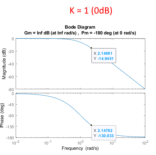
By far the easiest way is to investigate the open loop transfer function \$H_\text{ol}(s) = KG(s) \$. Initially, set \$K=1\$ and look at the Bode Plot: -

s = tf('s');
G = 1/(s+1)^2
K = 1
margin(G*K)

enter image description here

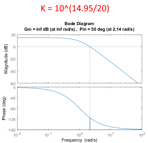
For \$50°\$ phase margin the crossover frequency has to be \$\omega_c = 2.14\: \text{rad/s}\$, as seen from the Bode Plot. This is achieved by increasing the gain to \$K=10^{\frac{14.95}{20}}\$: -

enter image description here

\$\endgroup\$

Your Answer

By clicking “Post Your Answer”, you agree to our terms of service and acknowledge you have read our privacy policy.

Not the answer you're looking for? Browse other questions tagged or ask your own question.