3
\$\begingroup\$

Good Morning everyone,

I have recently designed a circuitry design for the named chip "CP2102N-A02-GQFN24". Problems appear after connecting the chip to the computer. It doesn't get recognised properly. It shows that the connected device is not functional.

My guess is actually that there is problem with my circuitry. As the documentation wasn't too easy to read. And even after many hours of research, I am not too sure if VREGIN needs to be connected to VBUS or just to VDD/VIO. Do I need to connect pin 25 to Ground? Circuitry design of the CP2102 Everything looks fine? -> probably a soldering/component issue right?
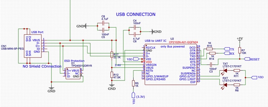
If more information is needed please remind me kindly.

Thank you for any help in advance.

EDIT: Note that this circuit is just for a bus-powered Application.

\$\endgroup\$
11
  • 1
    \$\begingroup\$ Why have you connected the Vbus on to a voltage divider instead of directly to Vbus? \$\endgroup\$
    – brhans
    Commented Aug 23, 2020 at 3:22
  • 1
    \$\begingroup\$ No, I think you got it right. The datasheet says the resistor divider is what you want for pin 8 in the "bus powered" configuration. VBUS does go directly to the VREGIN pin 7. I don't see anything wrong. What do TX and RX connect to? Make sure they're not swapped (easy mistake to make). \$\endgroup\$
    – td127
    Commented Aug 23, 2020 at 4:22
  • 1
    \$\begingroup\$ Yes, VREGIN goes directly to VBUS, as you have it in your schematic. Just to clarify, TX should go to RX on the atmega, and RX to TX. Or is the problem that the host never even recognizes that anything is connected (i.e. not showing up as a COM port in the Device Manager, assuming we're talking a Window host). \$\endgroup\$
    – td127
    Commented Aug 23, 2020 at 4:53
  • 1
    \$\begingroup\$ No, the rx/tx swap wouldn't prevent it from showing up in the Device Manager, so there's something else going on. Hmm... \$\endgroup\$
    – td127
    Commented Aug 23, 2020 at 5:41
  • 1
    \$\begingroup\$ Only the pins on the left side of CP2102 schematic are responsible for the USB connection. Do the easy things: check that VBUS = 5V, that 3.3V VIO is produced, and that the voltage divider is yielding 3.4V. \$\endgroup\$
    – td127
    Commented Aug 23, 2020 at 15:56

1 Answer 1

1
\$\begingroup\$

The constructed circuit is correct!

After repositioning the bypass Capacitors to a closer distance, problems with the recognition in Simplicity Studio and general of the chip have disappeared. My Capacitors wouldn't work with a trace length greater than 3 cm. (Doc.CP2102N Data Sheet: 2.1 - Figure)

Additionally I couldn't get the chip working when connecting to MacOS. Following Errors would constantly appear in Simplicity Studio:

Beginning import from device.
Error: DLL wrapper timed-out!
Errr: No response received from device!
Done! Elapsed time: (0:05.02)

When switching to windows everything worked fine.

Oh yea and don't make the same mistake with not switching RX/TX, when trying to communicate with other chips. Thanks to @td127

Also: Make sure to set the GPIOs (0,1) to TX/RX Toggle, to enable the LEDs. (Doc.CP2102N Data Sheet: 4.3.10)

Similar Problem in the forum of Silicon Labs: here

\$\endgroup\$

Your Answer

By clicking “Post Your Answer”, you agree to our terms of service and acknowledge you have read our privacy policy.

Not the answer you're looking for? Browse other questions tagged or ask your own question.