I got an induction motor in a junkyard, a WEG motor made for an Electrolux washing machine.
It is a single-phase 1/2 hp 4 pole motor. It runs in 127 V and has a 40 uf capacitor feeding the auxiliary winding.
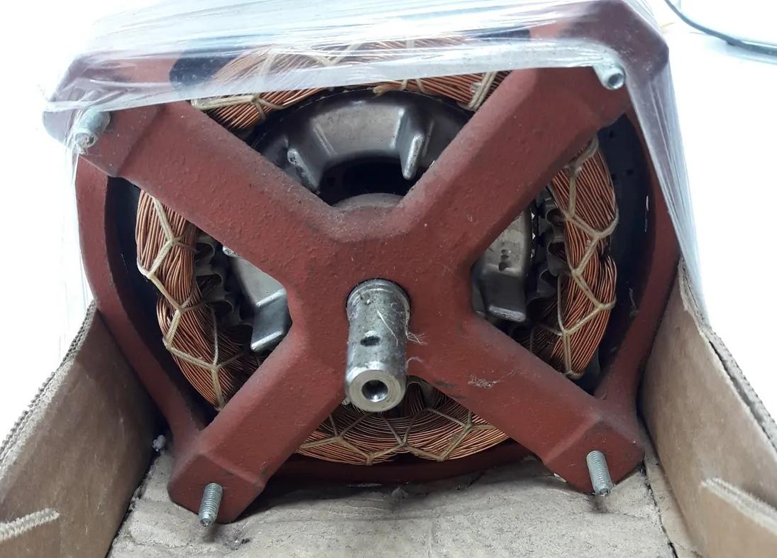
Here's a photo of an identical one I found on the internet (mine is currently disassembled):
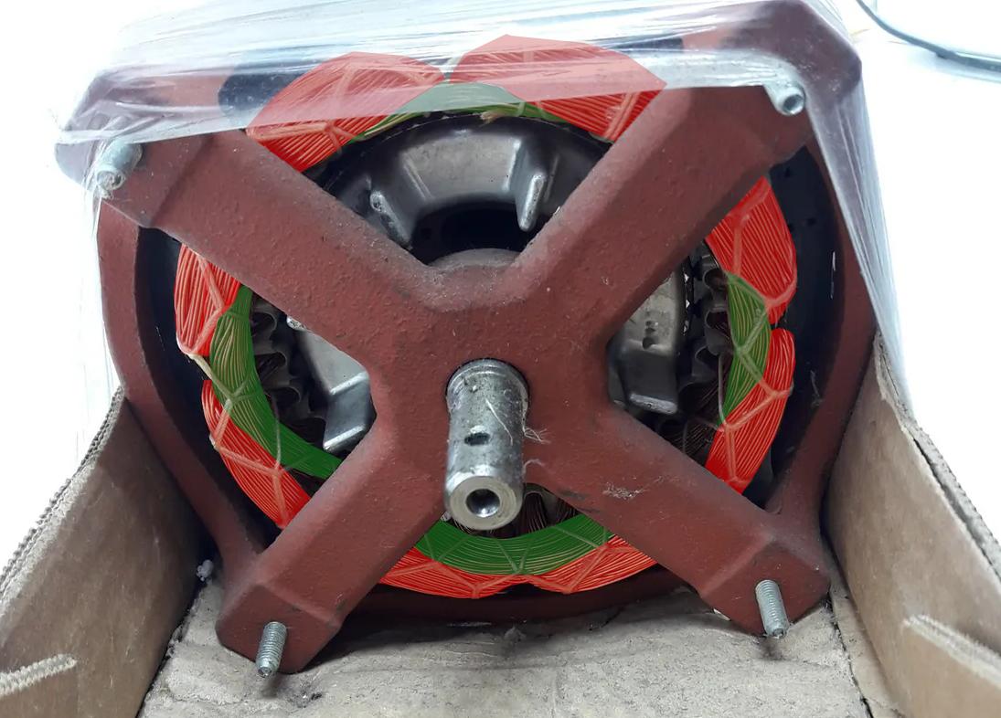
Its winding can be divided into 2 sets of 4 units each: The set of inner windings (green in the picture below) and the set of outer windings (red in the picture below).
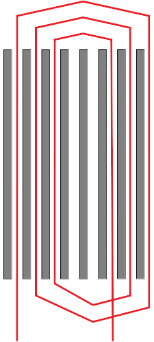
After several tests I could assure it was what It looked from visual inspection, a concentric winding scheme where each unit looks like this:
Furthermore, I found out the 4 outer units are wound with two wires in parallel, having the same number of turns and inductance of the inner ones, but half the DC resistance.
In each set (inner and outer) there are 2 units wound clockwise and 2 units wound counter-clockwise, interleaved.
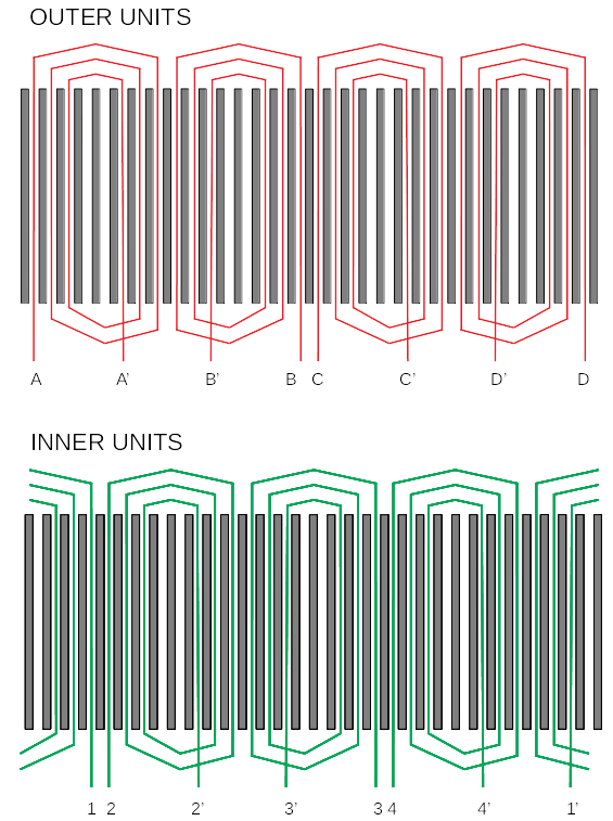
The stator has 32 slots, so the overall winding looks like this:
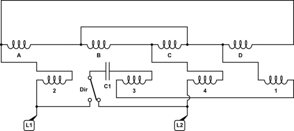
It originally came with these connections:
A'—B ; B'—C ; C'—D ; D'—1 ; 1'—2 ; 2'—3 ; 3'—4
The capacitor was connected between A and 4', and the electrical network was connected between 1 and A or between 1 and 4' (for the two directions of rotation).
So, now that you know the motor,
My question is:
Is there a way to reconnect this to create a decent 2 pole or 8 pole motor?
Does the fact it's a concentric winding brings this any special properties?
I'm asking this because I couldn't manage to connect the units in any way that produces a viable 2 pole or 8 pole field.
The first thing I tried was undoing all the original connections, connecting only A'—C' and the electrical network to A and C. That should make an oscillating 2 pole field (not a rotating one), starting it manually should do.
But it didn't. Besides the immense current this draw (around 20 A), it would only accelerate to a rotation like 800 RPM and no further. It also sounded like it had a terribly uneven torque.
Remember those outer units were wound with two wires in parallel, so I changed that to series and tried again. Now I had less insane currents but no luck getting it to run at anything around 3600 rpm.
I tried several other configurations, also using the inner windings together to try to create a 2 pole field. I tried many possibilities but the closest I got was a very strange behavior, while using an auxiliary winding set fed with a 10 uf capacitor, where it would first accelerate to ~1800 rpm and then jump to ~3600 rpm by itself. All of that while drawing ridiculous currents, always over 15 A.
I had a different luck with 8 poles, cause it would actually run at ~ 800 rpm, but again presented ridiculous currents, didn't have a decent torque and I couldn't avoid ridiculous currents.
Anyway, I'm not understanding how it can be failing even to make a 2 pole oscillating field. It looks like it's somehow producing additional poles.
Could the radial motion of the current in the concentric winding (from the outer turns to the inner turns and vice-versa) play any role in this?
Thanks!

