0
\$\begingroup\$

I am powering an electronic speed controller (ESC) driving a BLDC from a bench supply capable of supplying 40V at 128A. The maximum load the ESC presents is 42A.

The wires from the supply to my setup are about 3 feet long (long!), and thus I added a capacitor bank at the ESC end to protect the electronics on the ESC, since the inductance of the wires will create large voltage spike at the ESC. I use the supply's sense lines to ensure I regulate the voltage at the ESC end.

The supply started to misbehave recently, after months of use testing my ESC design. Initially, the ammeter on the supply stopped working. Now, I believe the supply is having difficulty regulating when the switching current load is high.

Is it possible that voltage spikes (maybe capacitor bank is undersized - need to confirm this) at the ESC supply input damaged the sense lines and control circuitry in the bench supply over time? Is there typically protection circuity to limit voltage excursions on these lines?

I found the the manual for this old Agilent 6684A supply, but at first glance, I didn't find these types of specs --I'll look more carefully. Are there typically specs provided on what sense lines can take, or how fast the supply responds to step changes to the sense line voltages, etc?

I have another supply to use, but I don't want to kill it as well overtime if I could be potentially damaging it testing the ESCs.

\$\endgroup\$
9
  • \$\begingroup\$ You need to ask a question and provide supporting documents and links that can be actually answered. \$\endgroup\$
    – Andy aka
    Commented Aug 26, 2020 at 16:23
  • \$\begingroup\$ Asumption: your ESC is sourcing the Power Supply when the motor is slowed down /braked and the Power Supply is not build to cope with another "supply" sourcing its outputs. \$\endgroup\$
    – schnedan
    Commented Aug 26, 2020 at 16:30
  • \$\begingroup\$ Does your speed controller have any regenerative capability where it will dump power from your motor load back into the supply? If so I only guarantee a lab supplies not designed to sink current. \$\endgroup\$
    – MadHatter
    Commented Aug 26, 2020 at 16:38
  • \$\begingroup\$ @Andy aka --I see about three questions in the last paragraph.... \$\endgroup\$
    – jrive
    Commented Aug 26, 2020 at 17:19
  • 1
    \$\begingroup\$ Well the incuctance of the motor will generate a current with reversed polarity as soon as you stop pumping energy into the motor and such break it even more. And your assumption is that all that current flows back to the motor. But if there are two possible pathes current will split always. And if - and only for a short period of time - the path to your Power supply has less imperdance than the path to the Motor... it will take that route. \$\endgroup\$
    – schnedan
    Commented Aug 26, 2020 at 18:49

2 Answers 2

1
\$\begingroup\$

Is it possible that voltage spikes (maybe capacitor bank is undersized

  • need to confirm this) at the ESC supply input damaged the sense lines and control circuitry in the bench supply over time?

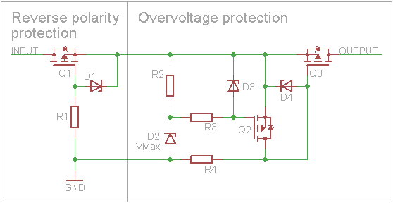
Yes, it is possible. It would be safe to assume that the supply does not have input protection for overvoltage. It would be best to use diodes or some other form of input protection like this circuit:
enter image description here
Source: http://kaktuscircuits.blogspot.com/2014/07/reverse-polarity-and-overvoltage.html

A better way would be to monitor the voltage spikes with an oscillocope at the input of the supply to see what your up against. Very short spikes could be taken care of with extra capacitance, or minimizing cable inductance and a diode. Very long spikes might need something like the circuit above. At any rate, it's probably not good to present voltage conditions beyond the rating of the supply to it's inputs.

\$\endgroup\$
5
  • \$\begingroup\$ thank you. Do you mean output of the supply? oh---perhaps you're talking about the sense line inputs.... \$\endgroup\$
    – jrive
    Commented Aug 26, 2020 at 17:40
  • \$\begingroup\$ Both should be protected, now that I think about it you are probably having issues with the sense lines, are the sense lines connected to the load with a cable in between? \$\endgroup\$
    – Voltage Spike
    Commented Aug 26, 2020 at 17:43
  • \$\begingroup\$ yes, the sense lines are connected at the end of the 3' wires at the input to the ESC board. I don't know what you mean by the power supply inputs ---input are the Mains, output is the DC I'm supplying to power the ESC. \$\endgroup\$
    – jrive
    Commented Aug 26, 2020 at 18:12
  • \$\begingroup\$ Such and similar ciruits are common in industrial equipment... but it protects an device from reverse polarity at the input and a buffer capacitor at the output side when input is 0V. If such a circuit is placed between the power supply and the ESC I doubt it has any effect - at least not for fast transients \$\endgroup\$
    – schnedan
    Commented Aug 26, 2020 at 18:45
  • 1
    \$\begingroup\$ @jrive sorry, I meant outputs. Part of the problem rests in the cable as the inductance would cause control issues for transients and switching loads. \$\endgroup\$
    – Voltage Spike
    Commented Aug 26, 2020 at 19:02
0
\$\begingroup\$

My suspicion is similar to the answer by @schnedan. When the motor speed is reduced, the ESC will attempt to transfer energy from the rotating mass to the DC supply. In addition, the inductance of the motor will cause the AC current to the BLDC motor to lag the voltage. The resulting reactive current is supplied as ripple current added to the DC source current. That must be supplied by the DC capacitor. The capacitor must be large enough to supply that without too much DC ripple voltage.

Note that the DC supply may have difficulty with the initial charge current of the capacitor. Some means of dealing with that must be provided.

In general, it would be better to supply the ESC from an unregulated DC supply. The ESC should be able to regulate its own output voltage with input voltage that fluctuates to the same extent that mains voltage fluctuates. However it would be useful to have electronic overcorrect protection supplied in the DC supply.

\$\endgroup\$
3
  • \$\begingroup\$ --thank you for your response. I will simulate the circuit again in LTSpice looking to see if I can observe what you are describing. With regard to powering the ESC from an unregulated supply, the reason I used the sense lines in the first place was to create a more controlled test setup for characterizing the ESC performance. The input supply to the ESC is directly connected to the "top" of the bridge, and I wanted to maintain a stiff rail (at least at the input of the ESC board) as different motors drew different peak currents. \$\endgroup\$
    – jrive
    Commented Aug 26, 2020 at 18:06
  • \$\begingroup\$ if you can expand more on your explanation of the reactive ripple current, and/or refer me to some documentation on it, I would appreciate it. thank you. For instance, see the comment I made above to MadHatter ---is my understanding of how current is flowing through the circuit during the PWM "off" time incorrect? I don't expect to see current flowing back to the supply, but I may be wrong here.... \$\endgroup\$
    – jrive
    Commented Aug 26, 2020 at 18:07
  • \$\begingroup\$ I think the important thing is the energy return due to decelerating inertia. The other issues are things to keep in mind, but I can't expand on them without looking at my references, I don't have time to do that. \$\endgroup\$
    – user80875
    Commented Aug 26, 2020 at 22:54

Your Answer

By clicking “Post Your Answer”, you agree to our terms of service and acknowledge you have read our privacy policy.

Not the answer you're looking for? Browse other questions tagged or ask your own question.