0
\$\begingroup\$

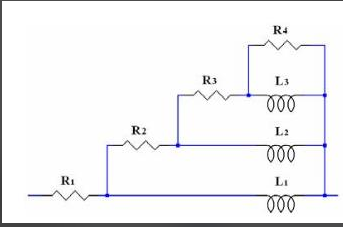
I am having problems trying to custom fit a frequency dependent behavior. I want to be able to convert a frequency dependent impedance Z(f) into an electrical circuit of the sort 1. The input of the code is the frequency dependent impedance Z(f) (real or complex) and the output will contain the values of the R_1, R_2, R_3, R_4, L_1, L_2, L_3 of the equivalent electrical circuit that will reproduce the same frequency behavior as that of Z(f). My question is: how can I compute the parameters of the equivalent model (seen in attached picture) to have the same frequency behavior as that of the input Z(f) ? Thanks in advance.

enter image description here

Photo here: 1 https://i.sstatic.net/hunlr.png

\$\endgroup\$
11
  • 1
    \$\begingroup\$ Do you have a question rather than a statement about how you are having problems? \$\endgroup\$
    – Andy aka
    Commented Sep 8, 2020 at 7:48
  • \$\begingroup\$ My question is: how can I compute the parameters of the equivalent model (seen in attached picture) to have the same frequency behavior as that of the input Z(f) ?. Thanks for your remark, I have just edited the post. \$\endgroup\$
    – Wallflower
    Commented Sep 8, 2020 at 7:53
  • \$\begingroup\$ Who says you can? Why do you think it's possible? Some things cannot be perfectly modeled and you have left no room for inexactness and neither have you said what you are trying to model. \$\endgroup\$
    – Andy aka
    Commented Sep 8, 2020 at 7:56
  • \$\begingroup\$ I know I can because I have found a scientific paper that does the same thing but does not mention how ... \$\endgroup\$
    – Wallflower
    Commented Sep 8, 2020 at 7:58
  • 2
    \$\begingroup\$ I do usually a "brute-force" curve fitting for this kind of task. I guess your input data is Z(f) is not given as analytical equation, so there is probably no point in going for clean analytical expressions. Can you provide an example of your Z(f)? \$\endgroup\$
    – UweD
    Commented Sep 8, 2020 at 8:12

1 Answer 1

2
\$\begingroup\$

As you already have a topology for the circuit, you have several options.

One option is to hand-analyse the circuit, into an expression in jω and the values of the components. This one has particularly simple form. Start from the parallel combination of L3 and R4 in parallel, let's call that Z3. Express the impedance of L3 as jωL3. Now Z3 is L3 in parallel with R4, Z3 = 1/(1/R4 + 1/jωL3). Now add R3 in series, and put that in parallel with L2, and continue up the ladder until you finally add R1, ending up with a power series in jω. It gets tedious, but it's possible.

Now compare expression power term by power term with your input expression Z(f), where f=2πω. If you have exactly the same powers of jω in each, then match the coefficients. If they result in consistent and non-negative values for L and R, then you have yourself an exact synthesis. Unless it's an exam question that has been contrived to work exactly, it's more likely that you'll have spare power terms, or get impossible component values, in which case you're doing a best fit approximation.

An alternative is optimisation, by either repeatedly analysing your circuit in Spice for instance, and tweaking values until the response matches Z(f), or by using optimising software which does that process quickly and automatically for you.

I'd recommend doing hand optimisation with SPICE first, to explore the landscape of possible values. If you let automatic optimsation rip without understanding the regions of values in which solutions will be reasonable and so being able to constrain the optimser, then they tend to disappear off to infinity, or down local rabbit holes, without getting to solutions you're happy with.

As you have a large number of scatterplots and want to fit each of them, you obviously need an automated solution. Whether an optimisation method performs well or badly depends strongly on the details of the problem. On the one hand, your R/L ladder should be quite low order and well behaved. On the other, small values for L1 would reduce the sensitivity of the input impedance to changes in the higher numbered components, which could confound automated solving. If the scatterplots are from measurements, then the noise on the measurements could also be over-fitted and so confuse an optimser.

I'd recommend starting with something simple like the Nelder-Mead Simplex method, it's a reasonably robust non-parametric steepest descent method. You would need to construct a 'distance' function to reduce the divergence between your scatterplot and the input impedance of your trial network down to a single number. The RMS or the minimax of the absolute differences are both popular measures, though whether you base them on linear or dB units depends on where you want the best fitting to occur. Do your scatterplots have phase information? Start with an 'average' of all your scatterplots if you can define such a thing. Observe what the optimiser does as it explores the surface to see whether you're on the right track. Set upper and lower limits for all of the components if you can. When in doubt, it's better to overconstrain the optimiser and then investigate the boundaries it's pushing against, than to underconstrain it and try to figure out where it's gone and why.

Before starting with a self-directing optimisation strategy like NM, I'd recommend a more robust and simpler method such as random. If you have a plausible range for each of the values, then let the computer do the heavy lifting and throw a large selection of random values from a uniform distribution of each of the component values at an analysis. Pick the best from 1e6 runs, then do it again several times. This will give you an idea of whether the problem is well behaved, or otherwise.

\$\endgroup\$
5
  • \$\begingroup\$ Neil_UK, thanks for the reply. Yes, I already have the analytical expression of the equivalent impedance of the target circuit shown in the picture above. Concerning the first attempt, I cannot do so since Z(f) is a scatter plot and not an analytical function. The second alternative is kind of unfit for my application, since I have 56 Z(f) scatter plots. Doing it by hand is surely not the best option. I am more interested in fitting scripts/algorithms that will enable me to custom my target fitting function and take an an input the scatter plot so as to automate as much as possible my work. \$\endgroup\$
    – Wallflower
    Commented Sep 8, 2020 at 8:39
  • \$\begingroup\$ @Wallflower I've added another paragraph. I'm not going to give detailed advice without seeing the data. I know 'get to know your problem' seems a bit lame, but machine optimisation is fraught with underspecifying its constraints, and then it goes off and meets them in an unexpected way. So you need to know at least roughly what the landscape of solutions is going to look like. \$\endgroup\$
    – Neil_UK
    Commented Sep 9, 2020 at 8:05
  • \$\begingroup\$ @NeilUK how can I share with you my scatter plot? I have a 500 points vector in my scatter plot which I obtained from a FEM simulation over the following frequency range: f = 1e6:1e6:4.99e8. The scatter plot is of real values only as the function is a frequency dependent resistor so no phase is defined. Based on the paragraph you've added, my objective function should be: Z_FEM(f)-Z_circuit(f) which should be minimized using NM method. Ok I will try this approach, thank you @Neil_UK! \$\endgroup\$
    – Wallflower
    Commented Sep 9, 2020 at 8:54
  • \$\begingroup\$ @Wallflower yet another paragraph, this is part of 'getting to know your problem'. If it's well behaved, lucky you, you'll get away with not needing to do too much work, it will solve itself. That large frequency range concerns me, the sensitivity to each of the component values will change with the frequency \$\endgroup\$
    – Neil_UK
    Commented Sep 9, 2020 at 10:49
  • \$\begingroup\$ Understood, thank you so much! \$\endgroup\$
    – Wallflower
    Commented Sep 9, 2020 at 10:50

Your Answer

By clicking “Post Your Answer”, you agree to our terms of service and acknowledge you have read our privacy policy.

Not the answer you're looking for? Browse other questions tagged or ask your own question.