1
\$\begingroup\$

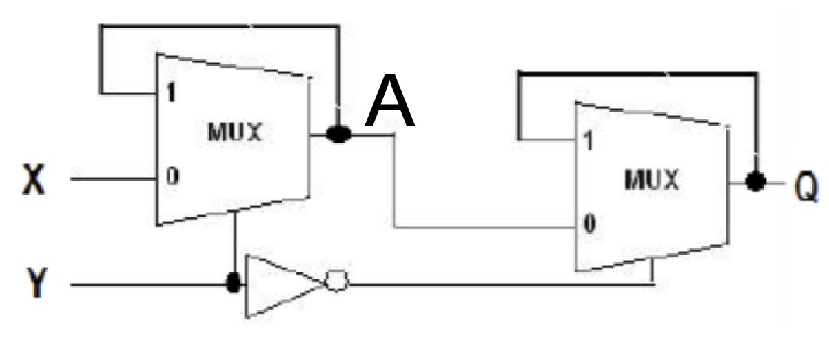
d flip flop implemented with 2X1 MUX

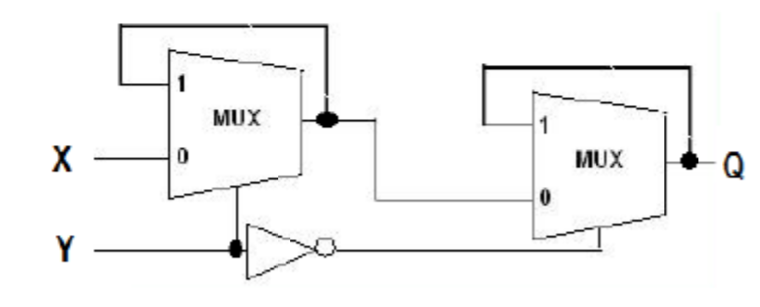
It is an edge triggered D flip flop where X is input, Y is clock, Q is output. Is this D Flip Flop positive edge triggered or negative edge triggered?

ADD (copied from a comment): Actually I am trying to learn digital circuits. While trying to do so I got stuck in this question. I know the answer of it (it is a positive edge level triggered D Flip Flop) but I cannot understand how can somebody deduce it from this figure.

\$\endgroup\$
9
  • 1
    \$\begingroup\$ Is this homework? What is your opinion, and why do you think so? \$\endgroup\$
    – AnalogKid
    Commented Sep 12, 2020 at 16:01
  • \$\begingroup\$ I am sorry I didn't get you. It is just a question I am unable to solve. It is not a home-work. \$\endgroup\$ Commented Sep 12, 2020 at 16:03
  • \$\begingroup\$ Describe how you think it works. \$\endgroup\$
    – user16324
    Commented Sep 12, 2020 at 16:07
  • 1
    \$\begingroup\$ It is a master slave d flip flop. The first MUX is the master D latch and the second MUX is the slave D latch. It is an edge triggered D flip flop where X is input, Y is clock, Q is output \$\endgroup\$ Commented Sep 12, 2020 at 16:10
  • \$\begingroup\$ Hi Anshul, please be honest with us. It is quite incredible that this is not homework. If you actually worked on some project for yourself or for work, then the whole question would be framed differently. Of course it's homework. I don't think people here like to help you if you are being dishonest. And everyone here knows that it's the time of the year when the new semester started. And also, people here want to help folks like you understand, not just blurt out the answers. \$\endgroup\$ Commented Sep 12, 2020 at 16:29

3 Answers 3

2
\$\begingroup\$

Start with a known initial condition for your inputs: X = Y = 0. From that it follows that A = 0 because the 1st mux is passing X to A. But Q is still unknown at this point.

Bring Y (clock) high. A was low and now remains low, latched. That low now passes through the 2nd mux so Y = 0. Now all nodes are in known states.

Bring Y back low. 1st mux's output doesn’t change. 2nd mux now latches, holding on to its 0.

Now bring X (D) high. A goes high but the 2nd mux doesn’t change.

Repeat by toggling clock (Y) and I wager you’ll find Q follows X on every rising edge.

\$\endgroup\$
0
\$\begingroup\$

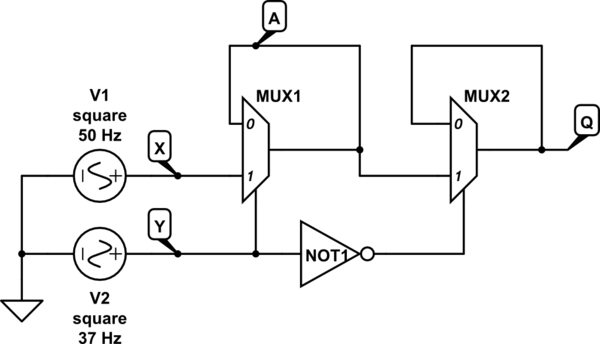
It's potentially triggered on both edges because it's a bad design.

schematic

simulate this circuit – Schematic created using CircuitLab

there's a race between not1 and mux1 if mux1 is faster it will trigger on rising edges and falling edges of Y if not1 is faster only rising edges will trigger it.

\$\endgroup\$
1
  • 1
    \$\begingroup\$ That's generally the way DFFs work -- there is potentially a race condition when the master latches and the slave follows. While not evident in this schematic, it is likely that the NOT is faster than the MUX. \$\endgroup\$
    – jp314
    Commented Apr 4, 2022 at 0:33
0
\$\begingroup\$

Homework. Either it must be done to pass a course or you are trying to learn digital basics by yourself. Nobody would get things like this as a paid work. Some guidance is available.

enter image description here

Check what should Y be to make A follow X. Then think when the state of A is transferred to Q and what's needed to happen until Q can get changed again.

Another useful thing to know: Every circuit has some delay. For ex. the output of the inverter stays stable few nanoseconds after the input has changed. Also the output of the multiplexer changes few nanoseconds later than the inputs if the new input states should cause some change in the output. But the delay in a mux is longer than in an inverter due more complex circuit. Without delays the circuit couldn't work nor understood.

Halt.

\$\endgroup\$
2
  • 1
    \$\begingroup\$ Actually I am trying to learn digital circuits. While trying to do so I got stuck in this question. I know the answer of it (it is a positive edge level triggered D Flip Flop) but I cannot understand how can somebody deduce it from this figure. \$\endgroup\$ Commented Sep 12, 2020 at 17:16
  • 1
    \$\begingroup\$ @AnshulGupta put that explanation into your post \$\endgroup\$
    – jsotola
    Commented Sep 12, 2020 at 18:58

Your Answer

By clicking “Post Your Answer”, you agree to our terms of service and acknowledge you have read our privacy policy.

Not the answer you're looking for? Browse other questions tagged or ask your own question.