0
\$\begingroup\$

The BTS7040 is a 2 channel High Side Switch with diagnostic feature, im planning on using 2 of the IC and i dont have extra GPIOs to spare.

The way you read a fault from the BTS7040 is to select a channel from the DSEL and read the current sense pin IS, if there is a fault IS will be at a fixed value (not sure).

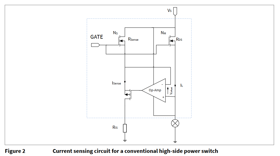
The Internal structure of the IS pin look like this taken from page 4 of it sensing datasheet

enter image description here

I can only allocate 2 GPIOs for the two BTS7040, 1 is used for the DSEL of IC and the other for the IS of both IC. I do not mind not knowing which channel and which IC the fault occurs all i need to know is that a fault occured. I am unfamiliar with the structure on how the IS pin is made thus i know nothing if it is possible to share a GPIO and if it is possible how to do it.

\$\endgroup\$

1 Answer 1

1
\$\begingroup\$

The IS pin provides a constant current proportional to the load current of the selected output, so if you connect two of them together you should be able to read the total current of both selected outputs.

Note this caution (emphasis added):

Due to the internal connection between IS pin and VS supply voltage, it is not recommended to connect the IS pin to the sense current output of other devices, if they are supplied by a different battery feed.

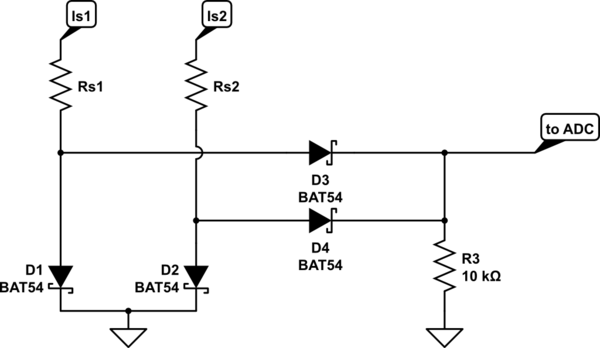
Edit: Alternatively--

schematic

simulate this circuit – Schematic created using CircuitLab

\$\endgroup\$
7
  • \$\begingroup\$ I should be safe then because both of the IC share the same VS supply. Wont it be hard for me to determine if one of the two share IS pin faulted, assuming the IS output 25mA at fault, a reading of 40 mA at IS would make it hard to determine if one or none faulted since it could be 20mA+20mA or 25mA+15mA \$\endgroup\$
    – Jake quin
    Commented Sep 13, 2020 at 18:02
  • \$\begingroup\$ You could add external comparator circuitry to each, with the result 'or' d to the input, but at that point maybe you want to do something to increase the number of GPIOs, like adding a shift register. \$\endgroup\$ Commented Sep 13, 2020 at 18:07
  • \$\begingroup\$ Or, very crudely, use two sense resistors and a Schottky diode OR gate with some load like 10K to ground, which will (more or less) give you the highest of the two currents. \$\endgroup\$ Commented Sep 13, 2020 at 18:28
  • \$\begingroup\$ I like the idea that I will read a digital rather than an analog signal, so i think ill go with the comparator approach. I have made a comparator circuit and stumbled upon the same situation... can i simply share the output like in the schematics? I still do not know yet the current it ouputs at fault so i could not make a voltage divider for the Vref. Can you check if my circuit is correct? \$\endgroup\$
    – Jake quin
    Commented Sep 13, 2020 at 18:30
  • \$\begingroup\$ That will work with an open-collector comparator such as LM393, however you need to swap + and - inputs so that the output is normally driven high by the reference. Then when either input exceeds the reference the common output goes low. 1K is a bit on the low side for the output pullup, 10K should be fine. \$\endgroup\$ Commented Sep 13, 2020 at 18:34

Your Answer

By clicking “Post Your Answer”, you agree to our terms of service and acknowledge you have read our privacy policy.

Not the answer you're looking for? Browse other questions tagged or ask your own question.