I am trying to describe the issue I have as clear as possible here:
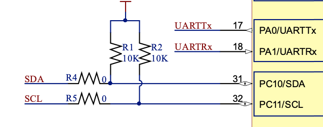
I have two self built development boards around a Silicon Labs EFR32 MCU. The boards are identical, but I encounter two different behaviors when using the boards and I cannot figure out what seems to be wrong. The connection between my I2C pins and the breakout pins looks as follows:
The I2c pins are also 5V tolerant going into the MCU. Now I connected my development boards to an MCP23017 GPIO expander and wired it up as described in the datasheet. With the first development board, communication was not problem whether the MCP was powered by 5V or 3.3V. But with the second development board communication was only possible while the MCP was hooked up to 3.3V, hooked up to 5V I just could not communicate. So next I hooked the I2C lines to my oscilloscope and suddenly the communication was no problem even though the MCP was hooked up to 5V. In the end it seemed like the MCP was always communicating, hooked up to 5V, as long as some conductive material was touching the SCL line even if it only was a screwdriver or an unconnected jumper cable.... I verified that all the components were properly soldered on both boards and that they had the expected characteristics. I still cannot make any sense of why my second development board behaves so weird. Maybe someone had a similar issue or might have any idea what the problem might be.
Any comment is greatly appreciated!
