This might be a wierd question but I was asked this in an interview. I know the basic behaviour of an RC network when it is connected to a battery (practical situation) and also the ideal situation when there is an ideal constant current source in series charging a capacitor (when the circuit is like a loop). However, what will happen if there is both an ideal current source along with a voltage supply in series with the capacitor. Edit: Added a picture, need to sketch the capacitor voltage at node A.
-
\$\begingroup\$ Please post a diagram \$\endgroup\$– mhaselupCommented Sep 24, 2020 at 9:15
-
\$\begingroup\$ @Nitesh Suryavanshi, And how did you answer the question? \$\endgroup\$– Circuit fantasistCommented Sep 24, 2020 at 11:02
-
\$\begingroup\$ I kindoff fumbled the question. I wasn't sure so I just said the voltage across the capacitor increases linearly like a ramp but said wasn't sure what happens when it equals the supply voltage. \$\endgroup\$– Nitesh SuryavanshiCommented Sep 28, 2020 at 10:23
-
\$\begingroup\$ But I think I have an idea. The supply voltage acts as some type of initial condition voltage for the capacitor right? \$\endgroup\$– Nitesh SuryavanshiCommented Sep 28, 2020 at 10:32
2 Answers
However, what will happen if there is both an ideal current source along with a voltage supply \$\color{red}{\boxed{\text{in series}}}\$ with the capacitor.
A voltage source that is \$\color{red}{\boxed{\text{in series}}}\$ with a current source is relegated to obscurity. You might just as well remove the voltage source and replace it with a short-circuit. The current source wins every time and defines the current flow.
On the other hand, a voltage source in parallel with a current source is different - the voltage source wins and defines the voltage; the current source is of no-consequence and can be replaced by an open-circuit i.e. removed.
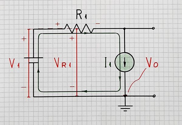
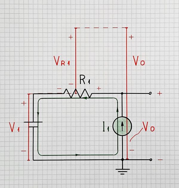
In addition to the Andy aka's answer, it would be interesting to consider the voltages in this arrangement in both cases - when the voltage source is connected in the same and opposite direction to the current source.
In the first case, the voltages of the capacitor and the voltage source are subtracted... and they determine the total voltage across the current source. It will continously increasing up to infinity.
In the second case, the voltages of the capacitor and the voltage source are summed. The total voltage across the current source will initially decreasing up to zero. Then, it will change (reverse) its polarity and will continously increasing up to infinity.
It is also useful to introduce a ground and to investigate the circuit when each of its nodes is connected to ground (a good question for another interview:)
I have explained a similar arrangement in another question - Why is the voltage drop created by a current source added? ...


... that maybe will be useful for you.
Think of the resistor as of a capacitor; if you are uniformly increasing the resistance, the resemblance will be amazing...
