1
\$\begingroup\$

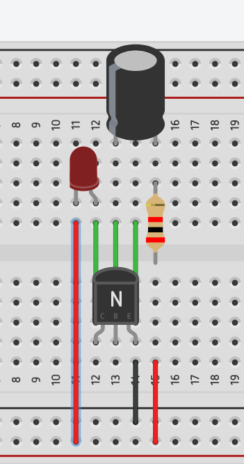
I built a switch on delay with a 2n2222 npn transistor and a capacitor.

Circuit

(I left out the base resistor (2k ohms) and the resistor for the led (330 ohms) in this simulation, but in real I added them for sure. The resistor before the capacitor is 1M ohm)

In theory, my 5V power supply should charge the capacitor slowly (because of the big 1M ohm resistor before the capacitor) and if the voltages reachs around 0.8V the transistor should switch on the led. Why is my circuit not working? I guess I forgot something since I have never seen such a small switch on delay on the Internet before. Or is the 1M ohm resistor in front of the capacitor too small to see a delay between plugging in my power supply and seeing the led going on? What is my mistake?

\$\endgroup\$
5
  • 2
    \$\begingroup\$ How about a schematic and not a cartoon? \$\endgroup\$
    – Andy aka
    Commented Oct 4, 2020 at 13:35
  • \$\begingroup\$ You have supplied a wiring diagram of your circuit. I recommend that you provide a schematic instead. This will reveal the schema of your circuit and the problems will be obvious if you've drawn it out properly. You can add one in using the CircuitLab button on the editor toolbar. Double-click a component to edit its properties. 'R' = rotate, 'H' = horizontal flip. 'V' = vertical flip. Note that when you use the CircuitLab button on the editor toolbar and "Save and Insert" on the editor an editable schematic is saved in your post. You don't need a CircuitLab account. \$\endgroup\$
    – Transistor
    Commented Oct 4, 2020 at 13:36
  • 1
    \$\begingroup\$ "(I left out the base resistor (2k ohms) and the resistor for the led (330 ohms) in this simulation, but in real I added them for sure." Don't do that. Show the circuit that we're trying to fix - not something a bit like it. \$\endgroup\$
    – Transistor
    Commented Oct 4, 2020 at 13:38
  • \$\begingroup\$ Also you have shown a 2K resistor where you claim the 1Meg resistor is. Also, how did you calculate the base current to supply enough collector current for the LED? \$\endgroup\$
    – user16324
    Commented Oct 4, 2020 at 13:52
  • \$\begingroup\$ Please show the circuit diagram with the exact component value, data provided creating confusion. \$\endgroup\$
    – Deepak
    Commented Oct 4, 2020 at 13:58

1 Answer 1

1
\$\begingroup\$

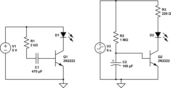
What you are doing is at left and what you must do is at right:

schematic

simulate this circuit – Schematic created using CircuitLab

\$\endgroup\$
4
  • \$\begingroup\$ Now it works, but still one question: How can I avoid the fading effect when the led turns on? \$\endgroup\$ Commented Oct 4, 2020 at 15:18
  • \$\begingroup\$ you mean when it starts to turn on? \$\endgroup\$ Commented Oct 4, 2020 at 15:22
  • \$\begingroup\$ yes, is this possible? I guess it is because the transistor does not output exacly high/low. At a certain voltage (the voltage, when the transistor starts switching) it outputs something between high/low and that is probably why the led does not turn on at full bright, but starts to fade in \$\endgroup\$ Commented Oct 4, 2020 at 15:26
  • \$\begingroup\$ Adding a zener diode (3.3V for instance) between C2 and the base (instead of connecting directly C2 to the base) increases the timescale and at the same time reduces the fading time. \$\endgroup\$ Commented Oct 4, 2020 at 15:41

Your Answer

By clicking “Post Your Answer”, you agree to our terms of service and acknowledge you have read our privacy policy.

Not the answer you're looking for? Browse other questions tagged or ask your own question.