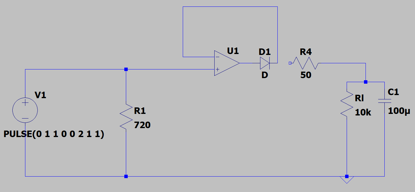
I'm currently designing a precision rectifier. I have a current sensor that outputs a current (AC) of 0.3mA to 32mA for 0-100A across a resistor of 510 ohms. As the value of the voltage will be around 0.3v for 1A of current, I can't just use a half-wave rectifier and rectifier the output and get the Dc value. I won't be able to sense current till it reached 5A or so. Hence I decided to design a precision rectifier.
The circuit is straight forward, didn't have any issue with simulation but when I actually implemented the circuit on a breadboard, I'm not getting the possible output.
The current sensor is sensing 11A current. It's outputting 2.2mA and I'm getting a voltage drop of 1.2V across a 510-ohm resistor. So far so good. Now I'm giving this voltage to the non inverting pin of LM358P. I'm measuring the same voltage at the output pin of the opamp. But when I measure the voltage after the diode (D1), I'm getting 2V for some reason. I'm getting the same 2V at the non-inverting input of the opamp too. I'm not sure where is it getting that 2V from.
When I connect the load resistor(Rl) and smoothing capacitor(C1), get 10V after the diode (D1). I'm not sure what I'm doing wrong?
I have attached the circuit to this email.


