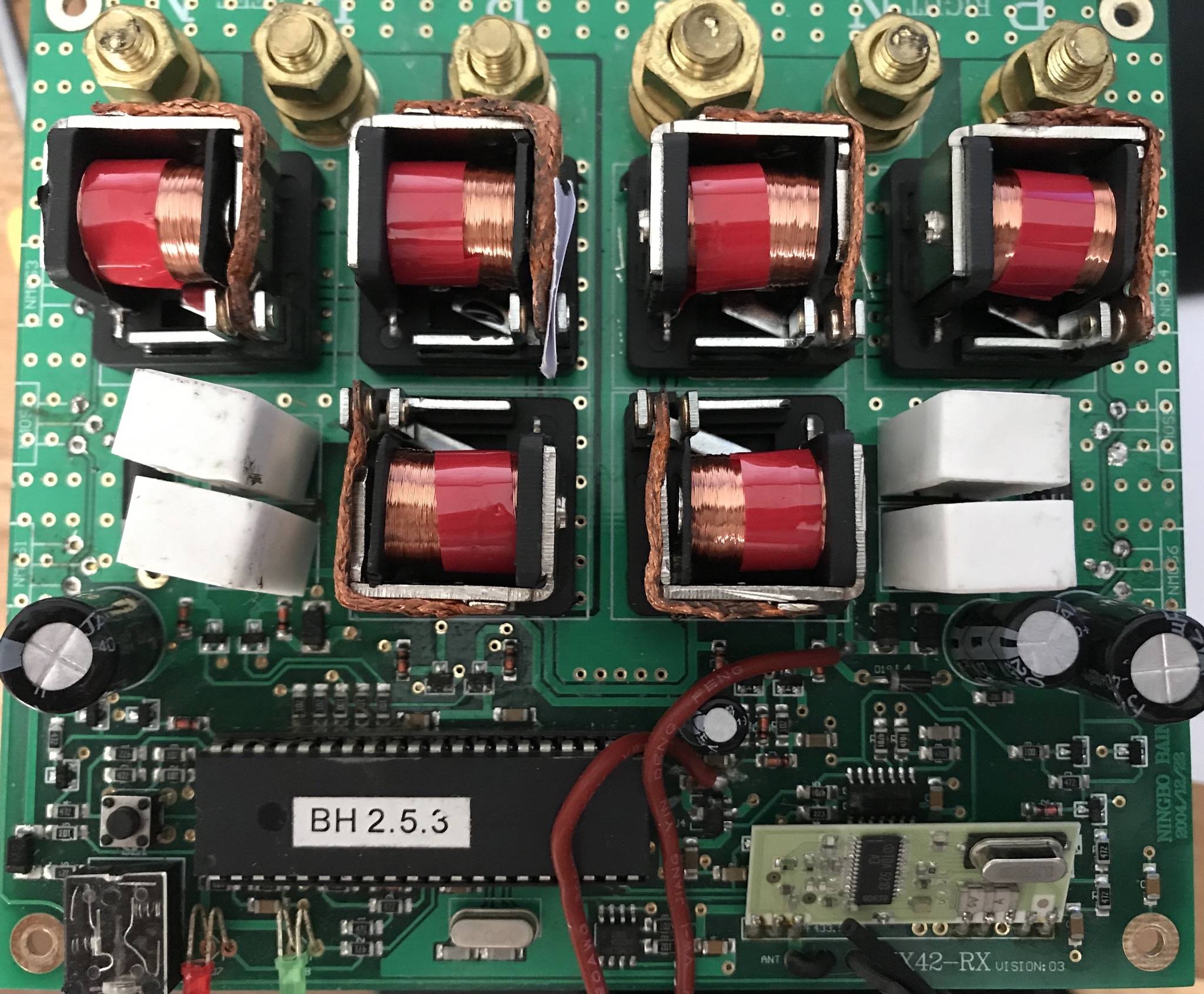
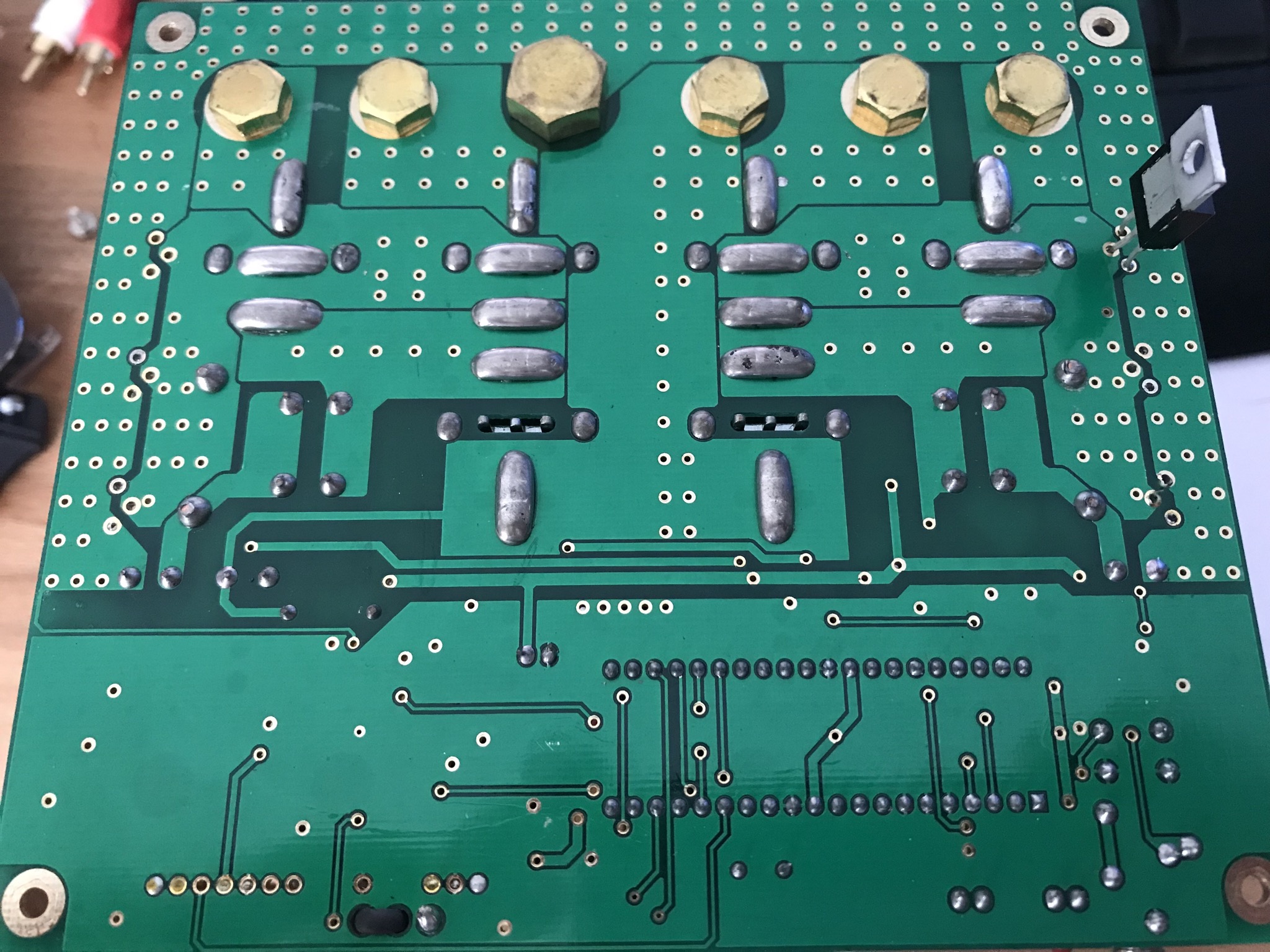
I've a motor control board here for controlling the motors that move a caravan. The board wasn't working properly so I thought I'd take a look at it. I'm definitely a newbie when it comes to electronics, but I'm not bad at understanding the electrical aspect of simple circuits..
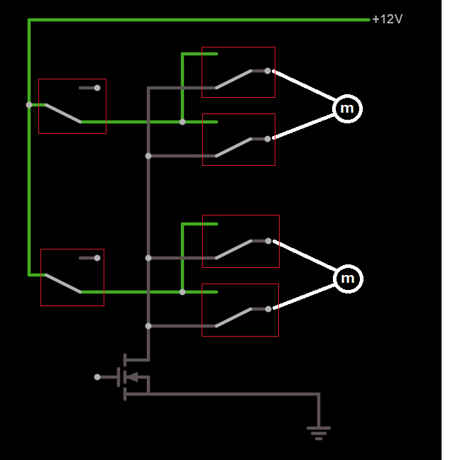
I traced out the relay connections as that seemed most logically how the motors would be controlled. The circuit looks like this, and the relays all function as I'd expect - a main power feed is switched on/off by two relays and from there feeds to a bank of 4 relays that are all off, and energise alternately depending on whether the relevant motor is to go forward or backward. The red boxes denote relays- i've left the coil rendition and the coil connections out because it's not needed for my question:
Main Question
Chiefly I'm curious why the ground/negative is supplied through (board can take six but only features four in parallel, only one shown in diagram) IRF3205 MOSFETs? Why does there need to be anything that switches the negative?
3 of the MOSFETs seemed dead - the D-S was OL regardless of whether the G had been prodded with the multimeter probe to activate it, and the 4th had some odd non-OL readings whether activated or not. I found a lower power MOSFET in a PC power supply and soldered it in as a tester, and the board neems to work sensibly now (on the bench) so I've ordered some replacements for the IRF3205s but I was puzzled as to why they were necessary
Pictures of the board in case they help:


Also, bonus question. When the controller is used, the sequence of events is:
- Push "turn clockwise motor 1" button on the remote
- Relay A for motor 1 energizes, supplying +ve to terminal 1 of the motor
- Relay B for motor 1 remains inactive, supplying -ve to terminal 2 of the motor
- If the button on the remote is released, Relay B briefly energises, meaning that both motor terminals are connected to +ve, then they both deactivate to the final resting state, meaning both motor terminals are connected to negative
What was the purpose of this brief "connect both motor terminals to positive" ?

