15
\$\begingroup\$

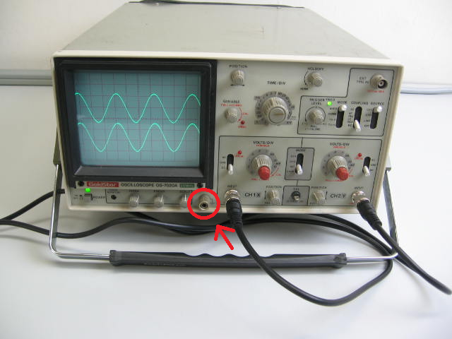
I just bought my first analog oscilloscope (GoldStar OS-7020A) and noticed it has a port on the front labeled "ground". What exactly is this port for?

I thought it might be for plugging in a ground clip for probes that don't have one included, but there are two channels and only one ground port, so I'm not sure. Is it simply for providing a convenient ground connection for other devices?

Could I, for example, attach my anti-static wrist strap to it? Would the oscilloscope have to be on for that to work? (Electronics newbie here, so please forgive me if this is a stupid question.)

GoldStar OS-7020A

\$\endgroup\$
3
  • 2
    \$\begingroup\$ Oh, and it's not limited to analog scopes, my digital scope has grounded probes. \$\endgroup\$
    – Thomas O
    Commented Oct 17, 2010 at 8:34
  • \$\begingroup\$ Out of all the answers, I still don't really see a good reason why there is a specific terminal for ground on some scopes. \$\endgroup\$ Commented May 24, 2012 at 7:17
  • 1
    \$\begingroup\$ @Cybergibbons - There is no "One Answer" as to why. Really, the only thing that can be said definitely is "Someone might want it, and it's cheap to add". \$\endgroup\$ Commented Jun 8, 2012 at 23:05

5 Answers 5

7
\$\begingroup\$

Most oscilloscopes have a safety ground. This connects to the earth ground on the plug and also to the case. The thinking is if you wire it up wrong worst case you trip the GFI/RCD instead of shocking yourself or damaging the instrument.

As an oscilloscope is usually a bench instrument it is not isolated from the mains. You can use an isolation transformer, but this is not recommended, as it removes this protection leaving the earth ground floating.

Tektronix sells an oscilloscope which has fully isolated inputs, I don't know of any other models. It is significantly more expensive to add high speed isolation circuitry. Usually it means the whole analog and acquisition side must be isolated.

The ground should always be connected to your circuit's ground or you will get strange behaviour. Trust me. I've spent hours looking at a trace wondering where the noise was coming from, just to find I haven't properly connected the ground.

\$\endgroup\$
17
  • 1
    \$\begingroup\$ Are you talking about the ground lead on the probe itself? I know that needs to be connected to the circuit's ground, but I'm referring to the separate ground port under the CRT screen (on the GoldStar, at least). \$\endgroup\$ Commented Oct 17, 2010 at 0:17
  • 4
    \$\begingroup\$ you want the probe's ground connected to something that's a good ground for the signal you're probing. i think if there's a ground on the front of the scope, it would be for referencing a supply or another instrument like a signal generator that could have isolated output. \$\endgroup\$
    – JustJeff
    Commented Oct 17, 2010 at 0:21
  • 2
    \$\begingroup\$ As long as it is plugged into the mains it should always be at earth ground. You can test this with a multimeter and the continuity test. \$\endgroup\$
    – Thomas O
    Commented Oct 17, 2010 at 0:25
  • 7
    \$\begingroup\$ I wouldn't connect a anti-static strap to it. Then entire point of the wrist strap is to route high voltage static spikes around sensitive electronics, why would you intentionally route it through your scope? \$\endgroup\$
    – Mark
    Commented Oct 17, 2010 at 0:33
  • 2
    \$\begingroup\$ Furthermore, I'm not too sure what you're talking about with an isolation transformer. They make everything safer, as there is no way to shock yourself by contacting any one point on the instrument, and ground. The only way to apply mains across your body is to contact both sides of the isolation transformer. Assuming you're not poking around inside the instrument with both hands, a good isolation transformer makes it very difficult to hurt yourself, as contacting any one point inside the device, even it if is a high-voltage rail, will not allow any current to flow.. \$\endgroup\$ Commented Apr 8, 2012 at 5:44
4
\$\begingroup\$

All of the existing answers here seem to be answering why you want to connect to the ground of an oscilloscope, not why there would be a separate ground terminal, therefore I don't feel too bad about posting the following piece of speculation:


The presence of a ground binding post is (I hypothesize) a legacy feature arising from the history of oscilloscope input connections.

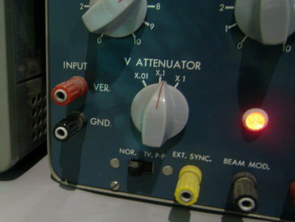
Once upon a time, coaxial cables and connectors were not so common and cheap, and the frequencies of interest were lower. Oscilloscopes had terminals for individual wires, or banana plugs, such as the binding posts on this unit:

Heathkit IO-12

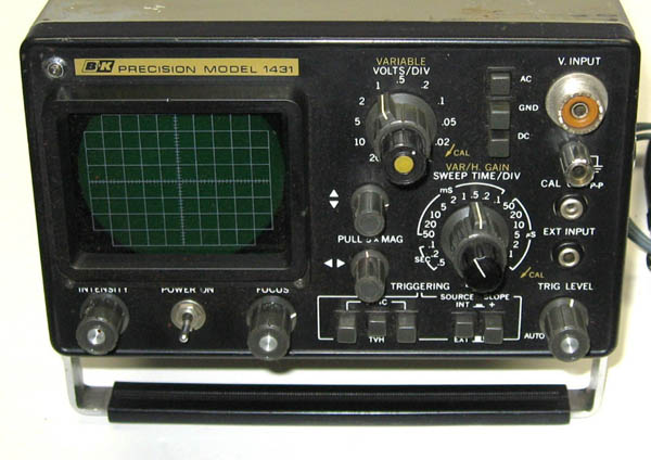
A later development was the SO-239 or “UHF” coaxial connector. One of the properties of this connector is that it can accept a banana plug. Therefore, if the scope has a SO-239 connector paired with a ground banana jack, it can accept either a coaxial or pair-of-banana-plugs input. An example of such a scope is the BK Precision 1431; note the jack and binding post in the upper right corner, with the same-sized center holes:

BK Precision 1431

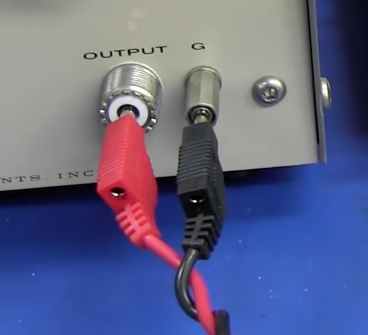
Here's a recent example of such a connection (not to an oscilloscope) actually in use, from one of Dave Jones (EEVBlog)'s videos. (This is a bit of a silly example, since the cable he's using is actually coaxial at the other end, but it was probably handier than digging up an adapter. SO-239/PL-259 is fairly uncommon if you're not an amateur radio operator.)

Two banana plug wires inserted in a SO-239 and binding post.

Thus I hypothesize that this feature was simply not removed (in some designs) when oscilloscopes transitioned to the BNC connector, which is electrically superior and more convenient to use but does not have the same banana plug compatibility.

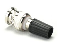
This vestigial connector is still potentially useful for banana or wire inputs; one can get a single-binding-post-to-BNC adapter (example below), or for that matter a SO-239 adapter, cheaper than the more commonly seen dual-binding-post adapter. But that is a fairly obscure use case and certainly doesn't justify keeping it around when modern oscilloscope use nearly always involves either a probe or a coaxial cable input.

\$\endgroup\$
3
\$\begingroup\$

That terminal is the case-ground of the oscilloscope.

Assuming your oscilloscope is using a three-pin plug, it is connected through the device's power-cord to ground.

It's generally used for controlling your ground-current routing, when you are trying to make high-precision measurements, which normally involves an isolation transformer (or several).

Assuming your bench is properly grounded, I don't see any issue with connecting your anti-static wrist-band to it. Do make sure that there is some resistance in the cable for your wrist-band, (I think ~1MΩ is common).
Otherwise, you will not only potentially damage anything with a static charge (you need to bleed off a static charge slowly), but in the case of any incident where you accidentally contact a high-voltage, through you you will be the shortest path to ground.


For what it's worth, you can use the oscilloscope's internal power supply as a poor-man's isolation transformer by cutting the ground lead on a power cable. This causes the whole scope to float, electrically, so you can measure with the scope-ground connected to a voltage rail without grounding the rail.

However, be extremely careful if you do this, as any fault on the non-isolated side of the scope's internal power supply could cause mains voltage to be applied to the scope local ground (and through this, your device, and potentially you).

I've done it, but it's kinda one of those areas where, unless you know enough to understand the risks (and therefore would not be asking this question), you should probably use a proper isolation transformer if you wind up needing one.
\$\endgroup\$
1
\$\begingroup\$

the additional grounding is for the equipment you are working on,additional chassis ground so to speak.

\$\endgroup\$
1
\$\begingroup\$

There are times when a direct connection from the scope to the frame of the unit being scoped can clean up a noisy looking signal that you are monitoring. There's no telling what kind of ground loop conditions you might run into, especially with very high frequency signals. An example of the latter here, was when I used to look at "ECL" level signals in a computer where signals on a backplane were less than 1 volt swings and rise times in the nanoseconds, it was difficult to see the true waveshape with a standard probe, and a special connection that fit on the end instead of the probe tip consisting of two 1 inch wires, one hot and one ground, was the only way to see the true undistorted waveshape. If you are scoping signals in a circuit that is isolated from ground, maybe an a/c regulator for instance, it might be neccessary to look at a signal where neither connection is in reference to ground. Here you would isolate the scope from ground ("floating" your scope) and connect the scope ground to a non-ground reference point to see a signal that is in reference to that with your probe. Ofcourse you have to be carefull doing this and make sure the scope is sitting on a surface that doesn't short its cabinet to ground (if it's metal). none of this is a common every day situation, just depends on what equipment you're getting into!

\$\endgroup\$

Your Answer

By clicking “Post Your Answer”, you agree to our terms of service and acknowledge you have read our privacy policy.

Not the answer you're looking for? Browse other questions tagged or ask your own question.