1
\$\begingroup\$

My first post here, sorry in advance if this question has already been covered. Being a computer scientist, my knowledge about electronics is limited, never had a formal education, a couple of courses when i was a student hardly qualify me as an electronic engineer, so please forgive me again if this question might appear basic (it probably is).

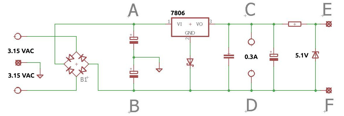
I am currently designing a simple regulated power supply given a center tapped transformer (lets assume a 3.15V-0-3.15V @ 5A secondary) and a SINGLE regulator.

enter image description here

So, having a bridge rectifier + filter caps i assume:

  1. A somewhere in the region of 4.4415V with respect to GND
  2. B somewhere in the region of -4.4415V with respect to GND

Now, lets assume the application calls for a) a specific voltage of 6.3V to power vintage tube filaments (DC, regulated, C-D) and b) 5V to power a simple MCU (E-F) from the same transformer winding.

Given the schematic (assume a TO-220 7806 as a regulator on a heatsink, 1n5817 schottky and a 5.1V zener), obviously, it has to be B=D=F, therefore i assume all to be at -4.4415V, right ?

In my case, there is actually no need for a negative voltage, is there a cheap/simple way (without introducing additional silicon, PCB space is an issue :-)) to elevate the negative rail (B/D/F) to GND while still being able to provide 6.3VDC between C and D (other than dropping the center tap) ?

Thank you very much in advance, regards

EDIT: numbers + concrete case description

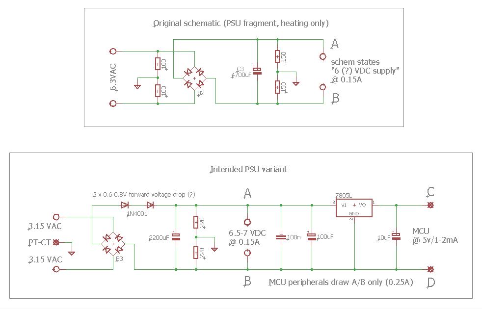
EDIT: Having considered posted suggestions (thanks to @fraxinus, @Marcus Müller for pointing out that the transformers voltage is too low for a decent regulation), i came up with an update that i hope to suffice for my application (see image).

enter image description here

\$\endgroup\$
14
  • 2
    \$\begingroup\$ D is directly connected to B and you already know what B is. \$\endgroup\$
    – user16324
    Commented Oct 24, 2020 at 17:47
  • 3
    \$\begingroup\$ Rather than talking about what the circuit does, please start at the beginning. What do you want the circuit to do? Why do you think that your circuit might satisfy your requirements? \$\endgroup\$ Commented Oct 24, 2020 at 18:09
  • 2
    \$\begingroup\$ Hi Nikolai! Welcome here. Small problem: WhatRoughBeast is right, you present us with a solution to some problem, but you haven't stated the problem you're trying to solve, so we can't really know whether where you're going is sensible (I do have my doubts!). \$\endgroup\$ Commented Oct 24, 2020 at 18:14
  • 3
    \$\begingroup\$ @NikolaiKim - Welcome :-) When asked for the real purpose of your PSU design, you said: "For the sake of this discussion, lets assume [...]" Nothing personal, but I really dislike that type of response. That's because it implies that the real purpose is something else which is being hidden from us. Too many times, I have seen questions where the real project is hidden, someone uses their valuable time to write an answer, and then it turns out that the answer is unsuitable - although it meets the stated requirements, it doesn't meet a previously-hidden requirement = wasted time :-( \$\endgroup\$
    – SamGibson
    Commented Oct 24, 2020 at 18:53
  • 2
    \$\begingroup\$ wait, where does the 6.3 V come from? That's new! and where's the 15.3 V gone? I'm super confused now? Can you please edit your question to really define what you want to do, and what voltages you need? I don't follow your 3.15 logic? \$\endgroup\$ Commented Oct 24, 2020 at 19:05

2 Answers 2

5
\$\begingroup\$

Nooooooo!

  1. The transformer

Looks like it is a vintage cathode heating transformer? 3.15 x 2 = 6.3 (the usual heating voltage). Except in pretty rare cases, you can power the filaments directly (and older designs do). Most of lamps are pretty tolerant about +/- 10% or so.

  1. The rectifier and the capacitors

These 4.4415V are more likely 4.0 if you are using Shottky diodes or 3.5-3.7 for the usual silicone rectifiers. Diodes have a forward drop voltage, remember. Doubled, it looks like 7.0-7.5V.

  1. The 7806 regulator These require at least 2.5V and better 3.0-3.5V (accounting for pulsations) more input voltage than the output, or they refuse to work. No 6.3V for your tubes.

  2. No enough room for the resistor and zener regulator, either. The output of 7806 will be less than 5V here.

Otherwise, solving all of the above, you can simply ground the negative rail instead of the center tap of the transformer.


Edit: how to improve the situation

  1. Lamps powered directly from the transformer (filaments are OK with AC).
  2. Single Shottky diode rectifier and single capacitor. You'll get near 8V at the capacitor.
  3. Either the same resistor + zener or a single 7805 or 78L05 and here you have 5V for the MCU.

Half the parts and all problems solved.

Edit 2:

Did you do something to regulate the anode power with respect to power fluctuations? If not, the heating not being absolutely stable may be way less of a concern since we are not talking about kW-range tube (these are picky and can go bad from either too high or too low heating). There are two other things to consider: there is some (capacitive) cross-talk between the heating circuit and the cathode. The heating transformer is center-grounded in order to get the cross-talk to self-cancel. ... or you will get hum. And second, you may as well still go with regulated DC heating, ground its negative and get rid of any hum, but keep in mind that all direct and even some indirect-heated tubes age faster when heated by DC (not sure if it applies to 12AX7). That's why if you power them with DC, you may want to create some means to switch its polarity once in a while.

All things considered, stick with AC heating.

If you need a common ground between the mcu-part and everything else, you are limited to using only one of the heating transformer legs. In this case, in order to get 5V, you may use voltage multiplier. You'll get 7.5-8V in respect to ground. Or two mulipliers, to keep everything absolutely symmetric.

\$\endgroup\$
11
  • \$\begingroup\$ Ok, thank you for your insight. My understanding was that having ca. 8V between A and B (6.3 * 1.3 = 8, representing a "loaded" case) is plenty for 7806 to stabilize properly. Adding a 1N5817 schottky would give a "close enough" voltage of ca. 6.3-6.5V :-( \$\endgroup\$ Commented Oct 24, 2020 at 20:20
  • \$\begingroup\$ The thesis here is that this transformer is meant to directly drive your filament, no diodes required. \$\endgroup\$ Commented Oct 24, 2020 at 20:23
  • \$\begingroup\$ Yes, all true, didnt account for the voltage drop of the diode bridge either. Amateur :-( \$\endgroup\$ Commented Oct 24, 2020 at 20:30
  • \$\begingroup\$ @NikolaiKim don't worry. You can power the lamps from the transformer directly and use 7805 to get 5V. Almost here. I'll add some to the answer. \$\endgroup\$
    – fraxinus
    Commented Oct 24, 2020 at 22:14
  • \$\begingroup\$ @fraxinus Thank you again for the detailed explanation, very helpful indeed and much appreciated. I think i am going to stick to a simple solution very similar to yours. Drop the regulator, remove the "virtual ground" by replacing the series of the filter caps by 1 and use 1 additional forward diode for an additional voltage drop. Just one question though. If i wanted to preserve the transformers center tap being GND, can i put the BDF rail on GND as well (assuming the cap connection is NOT grounded) ? I know i can leave this circuitry without GND, but that again doesnt appear very neat to me. \$\endgroup\$ Commented Oct 25, 2020 at 0:33
2
\$\begingroup\$

So, having a bridge rectifier + filter caps i assume:

  1. A somewhere in the region of 4.4415V with respect to GND
  2. B somewhere in the region of -4.4415V with respect to GND

I wouldn't count on it - the only thing ensuring that is the symmetricity of the capacitive coupling through the polarized caps between your "points" A and B. If there's more capacitors down the line, and they're not symmetrical (which is given by the fact that your schematic isn't symmetrical, this will not be the case.

It also doesn't seem to matter for your application, at all: the voltage of a heater filament doesn't have to be exactly GND-referenced; that usually makes no difference (the acceleration voltage of a tube is so much greater).

Now, lets assume the applications calls for a) a specific voltage of 6.3V to power vintage tube filaments (DC, regulated) and b) 5V to power a simple MCU from the same transformer winding.

This calls for two different regulators, very much.

The MCU is the easy part: throw in a linear 5V-regulator with its input voltage defined as between A and B, and you'll have 5V relative to the potential of B. Your microcontroller draws almost no current, probably, so that regulator will not produce much heat, and be very cheap, and still pretty stable.

It becomes a problem when your MCU's ground needs to be GND-referenced instead of B-referenced. Then, your rectified voltage is simply too low. The easiest solution is probably to replace the MCU with something modern that only needs e.g. 3.3 V, or you'll need some step-up converter, or a different tapping on your transformer.

Your heater filament, as mentioned above, usually doesn't have to be referenced to any specific potential. It's also perfectly symmetrical, and an ohmic load – instead of a voltage regulator, a series resistor (or a pair of two, half the value, if you want to keep the symmetry) would do.

\$\endgroup\$
1
  • \$\begingroup\$ Thank you very much for your reply. Concerning the filament reference, yes, true, however, my concrete subject is an amplifier that uses DC to heat up a double triode in its first preamp-stage. And for some (probably symmetry = audible hum) reasons (again, i am just a EE hobbyist :-) ) the filament supply is referenced (in one case via a PT center tap and in another via two resistors. I know - for a simple purpose of "heating" - it is probably best to drop the center tap entirely, however i would like to reproduce the original idea, hence the question. \$\endgroup\$ Commented Oct 24, 2020 at 20:05

Your Answer

By clicking “Post Your Answer”, you agree to our terms of service and acknowledge you have read our privacy policy.

Not the answer you're looking for? Browse other questions tagged or ask your own question.