0
\$\begingroup\$

I want to design a SDI-12 interface and I am using this schematic as a starting point. In receive mode, the 5V SDI-12 data signal will reach UART RX via the transistor Q1, but will also reach the output of the buffer U1 (I my case, it is a 74LV1T126GVH).

So, is there a risk of damaging the buffer when applying the RX voltage on its output? If so, what solution is there to this problem?

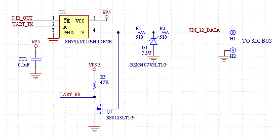
enter image description here

\$\endgroup\$
14
  • \$\begingroup\$ Paste the schematic into your question but leave the link for reference. \$\endgroup\$
    – Andy aka
    Commented Nov 4, 2020 at 12:25
  • \$\begingroup\$ @Andyaka I've included the schematic. \$\endgroup\$
    – Cristian M
    Commented Nov 4, 2020 at 12:29
  • \$\begingroup\$ Have you read the buffer datasheet if it allows it or not? \$\endgroup\$
    – Justme
    Commented Nov 4, 2020 at 12:37
  • \$\begingroup\$ Is the buffer active (OE low) usually ? Is it during this time that is your concern ? Have you added the 510R resistors yourself ? Is there a reason why you couldn't clamp the voltage to say < Vcc instead of the 7.5V ? \$\endgroup\$
    – citizen
    Commented Nov 4, 2020 at 12:48
  • \$\begingroup\$ @Justme The datasheet does not specify anything about applying voltage to its output. It only refers to inputs. \$\endgroup\$
    – Cristian M
    Commented Nov 4, 2020 at 12:55

2 Answers 2

0
\$\begingroup\$

The buffer will not work. And the schematic violates some of SDI-12 tranceiver requirements, such as DC impedance to GND.

The buffer will also not tolerate 5V on output if it is unpowered (VCC=0), so it will load down the bus outside the allowed limits of SDI-12 specs.

It needs an inverting buffer like in the example schematics, unless the UART_TX polarity can be set in the MCU. Sometimes UART polarity can be set, but is it separate for TX and RX is another question. As it is now, UART_TX and UART_RX will have opposite polarity, as the FET inverts the data.

Otherwise the schematic is almost a copy of reference design from SDI-12 standard.

\$\endgroup\$
3
  • \$\begingroup\$ Yes, you are right and thanks for noticing these issues. This schematic is a starting point; the 200k resistor and 3.3nF capacitor to ground are missing and I will add them. The buffer will not be powered off, so there will not be any issues regarding the tolerance to 5V. I missed the fact that SDI-12 uses a negative logic; however, I can't use that buffer (SN74LVC1G240) because it does not accept 3.3V signals when powered at 5V. I will invert UART TX with the inverting buffer 74LV1T04. Now, the TX and RX polarity should be fine on both sides (MCU and SDI-12). Please tell if you agree. \$\endgroup\$
    – Cristian M
    Commented Nov 5, 2020 at 18:05
  • \$\begingroup\$ I don't see the point of using two chips for this. If you go to chip manufacturer or distributor websites and do a parametric search for TTL compatible inverting three state buffers that work at 5V supply, I'm sure you find a suitable part. Maybe the MCU supports 5V levels so simply a pull-up to 5V is enough? \$\endgroup\$
    – Justme
    Commented Nov 5, 2020 at 18:32
  • \$\begingroup\$ The host is a I2C-UART bridge (MAX14830) and does not support 5V levels. Basically I need a 3-state inverting buffer with non-inverted enable input (active high OE), because it is controlled by !UART_RTS (which is not under my manual control). I've search several chip manufacturers' websites, but did not find a chip that meets these requirements. \$\endgroup\$
    – Cristian M
    Commented Nov 5, 2020 at 18:40
1
\$\begingroup\$

What you need is Tri-state buffers.

When one output or one input is not in use, it can be set as high impedance with the EN or -OE pins. And so the input or output is protected up to Vcc or even sometimes above that.

\$\endgroup\$

Your Answer

By clicking “Post Your Answer”, you agree to our terms of service and acknowledge you have read our privacy policy.

Not the answer you're looking for? Browse other questions tagged or ask your own question.