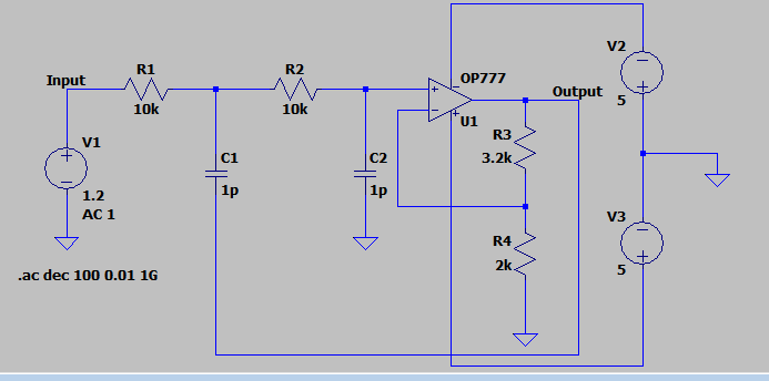
I was trying to do a project on LT spice for the frequency response for Sallen-Key low Pass filter.
But when I tried the Following circuit, I am getting a roll off 20db / decade instead of 40db/decade. Even I am getting a lower cut off frequency than expected. I had done this with 1 nF capacitor and circuit was behaving as expected.
Please help, I want an explanation for this deviation.
-
\$\begingroup\$ What is your target corner frequency? \$\endgroup\$– The PhotonCommented Nov 5, 2020 at 6:14
-
1\$\begingroup\$ Looks like a possible school project/assignment and you scrolled to the end of the opamp list and picked the OP777. If so, I suggest using the UniversalOpamp2 for simulations like these, as outlined here: electronics.stackexchange.com/questions/529510/… \$\endgroup\$– Ste KulovCommented Nov 5, 2020 at 6:51
2 Answers
First of all in your circuit you are using 1pF capacitors? this is too little for any practical circuit, even the parasitic capacitance of a PCB is higher. Second, with 1pF and 10Kohm resistors your cutoff frequency is 15.92MHz, the opamp you are using has a GBP of 0.7MHz, can you see a problem with this? with the specified gain the -3dB point of the opamp is around 270KHz, and if the opamp uses a single pole compensation the roll off will be 20dB/Dec, so what you are seeing is the opamp rolling off the gain long before it reaches the 15.92MHz cut-off frequency. With a 1nF cap the cut-off frequency is 15.92KHz, well within the bandwidth of the opamp.
The OP777 only has a gain-bandwidth product of about 0.7 MHz, but you are trying to use it in a circuit with gain of about 2.5 and cut-off frequency above 1 MHz.
The circuit response you are seeing doesn't even depend on capacitors. You'd see roughly the same if you removed the capacitors and just built a gain-of-2.5 non-inverting amplifier. (But in the real world, unlike the simulator, the cut-off frequency might vary from part to part)


