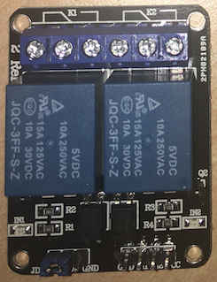
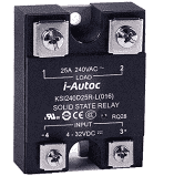
I have a Pulse PLA900 AB amplifier and I would like to use a non-latching relay switch to switch it on/off from a digital platform. Unfortunately, the technical data sheet of the amplifier lacks crucial information for my project, such as standby power (i.e. when there is no input signal to be amplified) or power consumption on full load, or peak power when the amplifier is switched on, therefore I can just guess them. The RMS is 760 W so with the assumption the efficiency of the amplifier as well as of the transformer is 80% then the maximum power consumption of the amplifier from mains is 10/8 * 10/8 * 760 W * buffer = 1187.5 W * buffer = 1500 W. I have no equipment to measure the peak power that the amplifier picks up when it is switched on but it has a 10 A fuse on the mains - which means nothing but this is what I have.
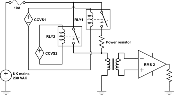
This is my simplified diagram, the starting point - I do apologise for its simplicity and imperfect nature, hope it is good enough for visualisation:
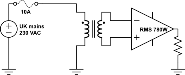
simulate this circuit – Schematic created using CircuitLab
I have tried a switching relay with no load on the amplifier, that was certified for AC 250V 10A, and the guess based on similar types its maximum switching power was around 200W, but it probably got welded because I was just able to switch it on/off like three times then it never switched off again.
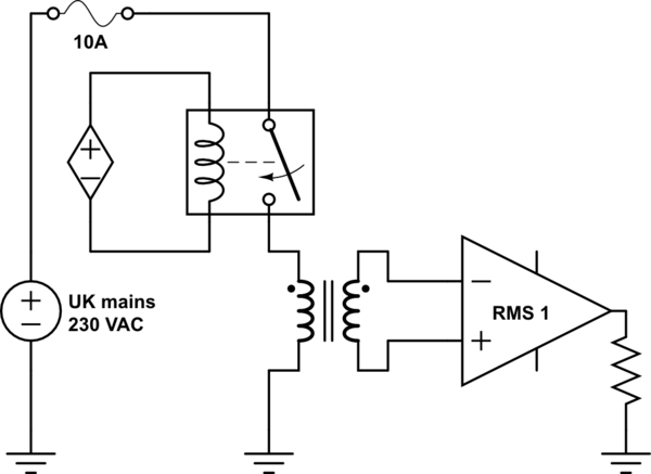
Someone then suggested to use two relays in parallel with a small power resistor (10 ohm 5 W) in series of the first, then for switching ON follow the below steps:
- switch ON the first with the power resistor
- wait 0.5 sec
- switch ON the second without resistor
and for switching OFF follow the same steps in reversed order:
- switch OFF the second without resistor
- wait 0.5 sec
- switch OFF the first with resistor
My questions as follow:
- Is this proposed method standard and safe?
- If this is standard and safe, then
- What would be the best way to calculate R and W of the resistor with the limited available of information?
- Which type of power resistor would suit best for this problem: cement or wire wound (aluminium case)?
- Would a relay with max switching power 2770VA 210W be sufficient? I have a 2 relay module handy, that data sheet could be this but unfortunately not sure https://www.generationrobots.com/media/JQC-3FF-v1.pdf
