1
\$\begingroup\$

I have a problem that I can't seem to wrap my head around.

I am designing a controller for a JBC handpiece, but the cartridgess are only three pins (JBC Nano only two.) I'm trying to design a controller that would be "universal" between the two (for now just focused on the C245 pictured below.) I'm using 24-45VAC.

enter image description here

I would measure the thermocouple at the "zero crossing", but how would I protect the circuitry when it is not at zero crossing?

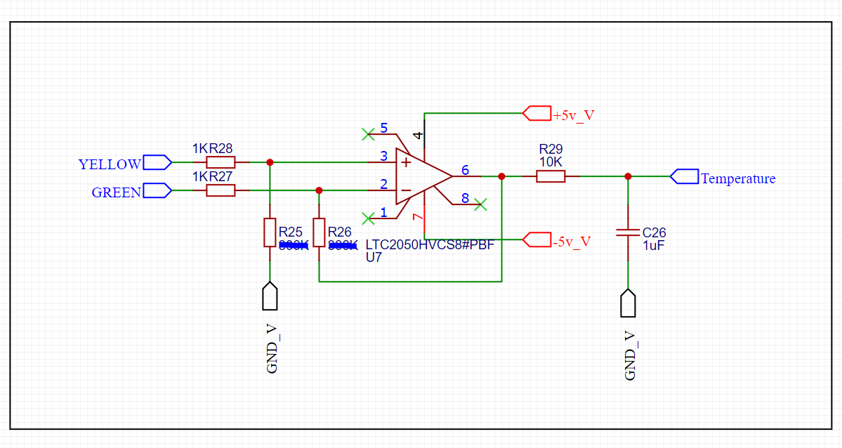
I have the basic AC MOSFET circuitry, current sensing, etc. all figured out (ready for testing,) but just can't seem to understand how I can measure the thermocouple correctly. I have seen many designs using "single ended" designs using diode protection, but wouldn't using an op amp in differential configuration be better? (Below is my rough circuit.)

enter image description here

Yellow = C1, green = C3, temperature goes direct to micro. (I'm using a "rail splitter" for my voltages, -5v_v is analog GND.)

I'd go into more detail but this is already fairly long.

TL/DR: How to amplify thermocouple signal when one leg is "common" to an AC heater element? Single ended vs differential vs something else.

\$\endgroup\$
4
  • \$\begingroup\$ Where is a lot schematics on web. But I think heating element 24VDC. \$\endgroup\$
    – user263983
    Commented Nov 28, 2020 at 23:41
  • \$\begingroup\$ The official jbc station uses ac voltage to the iron. Dc would be easyer but that has issues with efficiency, tip degradation etc. \$\endgroup\$
    – super7800
    Commented Nov 29, 2020 at 0:22
  • \$\begingroup\$ I would expect that to be an RTD, not a thermocouple. The terms are not interchangeable. \$\endgroup\$
    – Transistor
    Commented Mar 19, 2023 at 17:22
  • \$\begingroup\$ It pretty much has been confirmed by dozens of others, including myself, that it is just a weird thermocouple. Thanks for the suggestion though! \$\endgroup\$
    – super7800
    Commented Mar 20, 2023 at 18:54

1 Answer 1

1
\$\begingroup\$

Nichrome to copper has a Seebeck coefficent of around +18.5 uV/K and the heater may be rather hot relative to the soldering iron tip, so I don't think it's a particularly good idea to include the heater in the thermocouple measurement circuit, though it would probably still work similarly just worse. Follow whatever the original designers of the tip did, would be my suggestion.

If the heater current is zero there will not be any voltage drop across the C1 wire during the measurement phase. You do have to ensure the measurement circuit recovers from overload (presumably diode-limited) and settles quickly enough for an accurate measurement before the heater has to be turned on again.

\$\endgroup\$
2
  • \$\begingroup\$ The tip only has 3 pins, so it has to be measured from c1 to c3, and powered from c1 to c2. Also since its ac all measurements would be done at the zero crossing point. I'll look into diode limiting for my above circuit thanks. Perhaps single ended would be better? \$\endgroup\$
    – super7800
    Commented Nov 29, 2020 at 0:35
  • \$\begingroup\$ Yes, single-ended is fine since there's not another wire to use that doesn't connect through the heater. \$\endgroup\$ Commented Nov 29, 2020 at 2:04

Your Answer

By clicking “Post Your Answer”, you agree to our terms of service and acknowledge you have read our privacy policy.

Not the answer you're looking for? Browse other questions tagged or ask your own question.