5
\$\begingroup\$

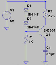
In my other topic i asked on how to create a sawtooth signal and guys on the forum gave me an excelent anwser. But! I cannot fully understand the first part of a circuit which is supposed to be an "constant current source". I know in theory what it should do but i cannot seem to understand this circuit:
enter image description here

Correct me if i am wrong but i think that capacitor is where a constant current's load should be. And current through load should be constant... This is all i know (for now) and i want to know how exactly does this circuit achieve constant current through a capacitor? I know allso that current doesn't actually flow and that sooner or later when capacitor reaches saturation current stops.

\$\endgroup\$
3
  • \$\begingroup\$ Look up "current mirror" on Wikipedia. While this circuit you have here is not a current mirror, it is similar enough that reading the wiki page will help you understand things. \$\endgroup\$
    – user3624
    Commented Jan 10, 2013 at 20:50
  • \$\begingroup\$ Q3 should have a current limiting resistor (say 10R) in series with C1 to keep the collector current below 200mA. \$\endgroup\$
    – user25993
    Commented Jul 3, 2013 at 17:15
  • \$\begingroup\$ @JimG.: Isn't the current already limited to <2.3 mA by R2? And if R1 were larger, wouldn't base current * max current gain of 300 also limit the output current? \$\endgroup\$
    – endolith
    Commented Jul 15, 2013 at 15:26

3 Answers 3

7
\$\begingroup\$

The voltage across a capacitor is the integral of the current through it. If you feed a constant current to a capacitor, its voltage ramps up linearly, which is exactly what you want for a sawtooth waveform generator.

Yes, you're correct that this cannot continue forever; the complete waveform generator circuit will be discharging the capacitor periodically in order to prevent the constant-current circuit from saturating.

In the circuit you show, D1, D2 and R1 provide a voltage reference, in this case, approximately 1.2V, which is the total forward drop across the two diodes. This establishes the voltage across the B-E junction of Q1 and R2. Since the voltage across the B-E junction is also a diode drop, or 0.6V, this means that the remaining voltage, 0.6V appears across R2.

From Ohm's law, we now know the current through R2, 0.6V/2200Ω = 273µA. This is the current that is charging C1.

The voltage across the capacitor is a function of time: V = I×t/C. Let's rewrite this as V/t = I/C, which means that the rate of change of the voltage is the current divided by the capacitance. In this case, 273µA/0.1µF = 2730 V/s, or equivalently, 2.73 V/ms.

\$\endgroup\$
3
  • \$\begingroup\$ What about other elements of the circuit? What does 2 diodes, R1 and a PNP do? How do they function together. I need a full picture. I know that R2 is there to set the time until saturation of C1. \$\endgroup\$
    – 71GA
    Commented Jan 10, 2013 at 19:02
  • \$\begingroup\$ @71GA: See the text that I added to my answer. \$\endgroup\$
    – Dave Tweed
    Commented Jan 10, 2013 at 19:59
  • \$\begingroup\$ $$\frac{\textrm{d}V}{\textrm{d}t}$$ is a linear function which i can see yes. Thank you! \$\endgroup\$
    – 71GA
    Commented Jan 11, 2013 at 10:26
5
\$\begingroup\$

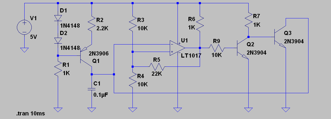
I'm going to bring the full schematic back into consideration: Original schematic

C1 is indeed the load. Current does flow - but you are right that when the capacitor reaches saturation current stops. However, before that happens, the rest of the circuit comes into play, and turns on Q3 for a while. That discharges the capacitor. Current is still flowing through Q1, but much less than through Q3.

Imagine a tap filling a bucket which periodically tips over and empties.

\$\endgroup\$
1
  • \$\begingroup\$ I know all this this. I don't understand ONLY the first part. \$\endgroup\$
    – 71GA
    Commented Jan 10, 2013 at 18:59
1
\$\begingroup\$

This first part of the circuit works as follows:

  • Assume C1 is discharged to begin with.
  • R1 just lets current flow through D1,D2 (serves as bias resistor), which ensures a known voltage at the base of Q1, since diodes drop a constant voltage.
  • Since we know the voltage at the base of Q1, we also know the voltage at its emitter (it behaves as diode), which means we know the drop at R2. It ends up being the same a a diode's voltage drop. Another way to put is is look at the drops from the two branches: D1-D2 and R2-Q1base. Since the diodes drop approximately the same voltage (including Q1's Vbe), then the voltage dropped by R2 will be the same as a diode's drop.
  • Since we know the voltage dropped by the R2, we know its current.

    The current is then: $$ I_{R2} \approx V_{diode}/R2 $$

  • This current will charge the capacitor C1, and the voltage described will be a linear ramp, because the voltage in a capacitor is proportional to its charge, and we are charging it a constant rate.

  • The capacitor C1 will get charged until its voltage, which is the same as the transistor's collector voltage, gets high enough that Vce is too low and Q1 it is not able to provide any more current (hFE drops to zero).
  • In the complete circuit, this voltage will trigger a discharge before this point is reached, and the process repeats.

You see then that the saw tooth signal is generated by the ability to generate a constant current that charges the capacitor, which generates a voltage ramp. Another way to put it is that we generated a constant signal (the current), and integrated it (with the capacitor), generating a ramp (the capacitor's voltage).

\$\endgroup\$
1
  • \$\begingroup\$ In the full circuit is it important to discharge the capacitor before saturation as there function V(t) isn't linear anymore? \$\endgroup\$
    – 71GA
    Commented Jan 11, 2013 at 10:24

Your Answer

By clicking “Post Your Answer”, you agree to our terms of service and acknowledge you have read our privacy policy.

Not the answer you're looking for? Browse other questions tagged or ask your own question.