5
\$\begingroup\$

I have a small SMD MOSFET [AO3400A] powering a small 12VDC motor which draws 1Amp in normal running mode (higher on turn-on but I can't easily measure that). When turning on this motor, it trips the power surge protection in my PSU. When I pre-load the PSU with other components, there's no trip-out. So, I want to soft start it, with as few components as possible.

I have built the attached circuit which works perfectly for non-inductive loads (eg 70W LED COB); the light comes on slowly. However, with a motor it blows the MOSFET so that when 3v3 is removed the motor continues to run (at half speed). Interestingly [with a new MOSFET], when the 20k resistor bypassed the motor starts immediately, and then ramps down as the cap discharges ... as expected. But why would adding RP3 to slowly charge the capacitor cause the MOSFET to blow?

Using a STP16NF06 TO220 MOSFET does not have this problem.

The PSU is rated 150W, and others on my desk of the same model don't trip... but I need to design to deal with the odd sub-standard PSU. In normal running the PSU is fine up to 12 amps.

I am powering the 3V3 with a microcontroller so I could in theory use a PWM start, but would that prevent the inrush current problem? I would suspect not.

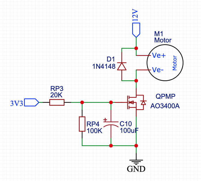
enter image description here

\$\endgroup\$
5
  • \$\begingroup\$ Do you have the part number of the motor? \$\endgroup\$
    – TimWescott
    Commented Dec 11, 2020 at 15:51
  • \$\begingroup\$ @TimWescott I don't but it's very similar to a 540; it's in a small submersible motorhome water pump. The problem appears to be with a few different pumps of a similar size. I would have thought a large starting current would be worse when I hard-started the motor rather than soft start with a voltage ramp? \$\endgroup\$ Commented Dec 11, 2020 at 15:58
  • 1
    \$\begingroup\$ Do you have part number for the PSU? But yes, turning a FET on slowly causes it to dissipate a lot of power. In your case, the resistors and 100uF capacitor will turn FET on extremely slowly, and it will dissipate too much power and melt. The 1n4148 is also incapable of repetitively handle the 1A peak currents when FET turns off. \$\endgroup\$
    – Justme
    Commented Dec 11, 2020 at 16:09
  • 1
    \$\begingroup\$ If you PWM the thing at a high enough frequency, you can PWM -- and if you do it right, you can probably use the itty bitty FET to do it. \$\endgroup\$
    – TimWescott
    Commented Dec 11, 2020 at 16:15
  • \$\begingroup\$ Just so you know, that's not really considered a soft-start, at least not a proper way. If it's considered a soft-start then it's the kind so crude that very few would ever consider actually using it. \$\endgroup\$
    – DKNguyen
    Commented Dec 11, 2020 at 23:09

3 Answers 3

8
\$\begingroup\$

On switch on you are probably holding the MOSFET in part of its operating characteristic where it exceeds its maximum power dissipation. Given the long time constant this may be a point where the motor does not yet start. The fact that the circuit works without RP2 and works with a TO220 FET capable of higher short term dissipation backs this up.

What strikes me is that you have a 2s time constant on the gate (given a low impedance drive) you don't need anything near that to start a small motor. Try reducing your gate capacitor to 10uF.

\$\endgroup\$
1
  • 2
    \$\begingroup\$ Thanks @RoyC - you're right, a smaller cap helps. I only have 1uF and 100uF lying around! I understand the principle now of needing to get through to max-on fast but not too fast. \$\endgroup\$ Commented Dec 11, 2020 at 17:04
13
\$\begingroup\$

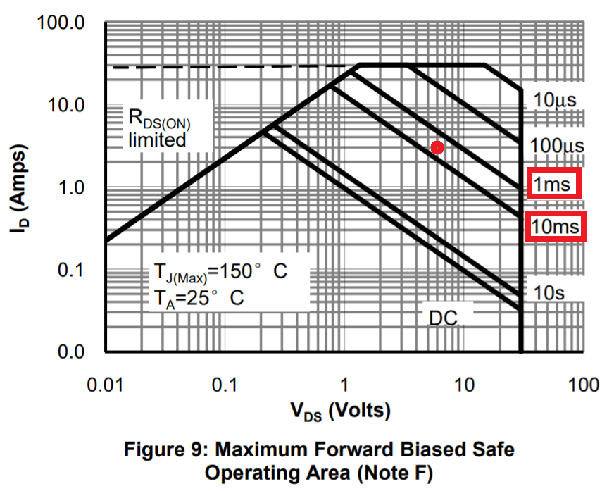
Given the very low speed at which you are activating the MOSFET, it will spend considerable time in the operating area where it is dropping about 6 volts from drain to source whilst consuming a current that might be as high as 3 amps.

I’m thinking here of the motor being stalled prior to the MOSFET turning on enough to get it actually rotating. It’s not unreasonable to assume that the motor might take 3 amps with 6 volts across it before it starts moving. 6 volts will also be across the MOSFET while in this state and that’s a power dissipation of 18 watts quite possibly.

On the safe operating area graph, this point is indicated by a red circle: -

enter image description here

The graph tells us that if the MOSFET is at 3 amps and 6 volts (half the supply rail) for longer than somewhere between 1 ms and 10 ms, you are going to possibly cause damage to your MOSFET.

Given that the RC time constant is 2 seconds, it's quite likely that you are well into the "unsafe area" for tens if not hundreds of milliseconds.

\$\endgroup\$
1
  • \$\begingroup\$ Aha a downvote. Anyone care to share a reason? \$\endgroup\$
    – Andy aka
    Commented Dec 11, 2020 at 19:27
5
\$\begingroup\$

The zero-load current on the motor is much bigger than the zero-load current on your LED, and you're burning up that poor little FET. Chances are that you're abusing the STP16NF06 that doesn't blow up.

Here's a pair of rough equivalent circuits of the LED and the motor plus its load.

I'm guessing a bit on the values for the LED, but I'm not guessing about the part that -- for the purposes of how it works -- it'll tend to look like a healthy voltage in series with a resistance. So the initial voltage drop across the thing will be much higher at moderate currents than the motor -- this will result in a lower drop across your FET, and less power dissipation. And if I'm wrong about the values for the LED, it's a higher voltage and a lower resistance, meaning that the thing stresses the FET even less.

The motor, on the other hand, is going to present a much greater load to the FET when it's not moving. In this case, the motor looks like an armature resistance (I'm guessing at \$100\mathrm{m\Omega}\$). When you first apply current to the motor, before it's moving, it presents a low resistance load. This means that for a given current, with the motor not spinning, the FET will see a much greater voltage. This will heat it up internally, and you'll let out the magic smoke.

The STP16NF06 isn't burning up because it has higher thermal mass, and thus stays cooler.

(The circuit, as drawn, models the motor coming up to speed as the capacitor charging up -- so once the motor is up to speed then most of the motor power goes into the mechanical load, which appears as a resistance in the equivalent circuit).

schematic

simulate this circuit – Schematic created using CircuitLab

\$\endgroup\$
2
  • 1
    \$\begingroup\$ Measuring motor resistance with ommeter we can calculate start current. \$\endgroup\$
    – user263983
    Commented Dec 11, 2020 at 17:15
  • \$\begingroup\$ @user263983 yes, but for the cheap motors you sometimes have to have it rotated just so -- I didn't want to complicate things. \$\endgroup\$
    – TimWescott
    Commented Dec 11, 2020 at 17:52

Your Answer

By clicking “Post Your Answer”, you agree to our terms of service and acknowledge you have read our privacy policy.

Not the answer you're looking for? Browse other questions tagged or ask your own question.