1
\$\begingroup\$

I want to control ME-4340 Syncube Non Spring Return Modulating Valve Actuator - 0/2-10Vdc ME-4340 with an STM32.

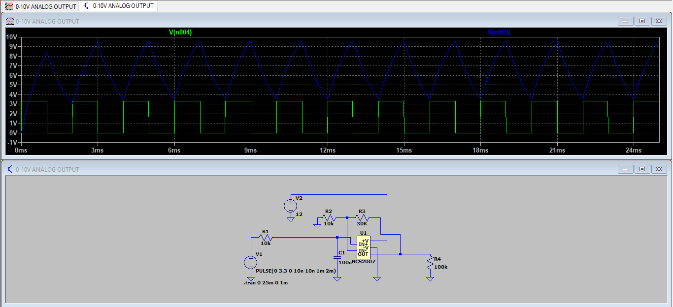
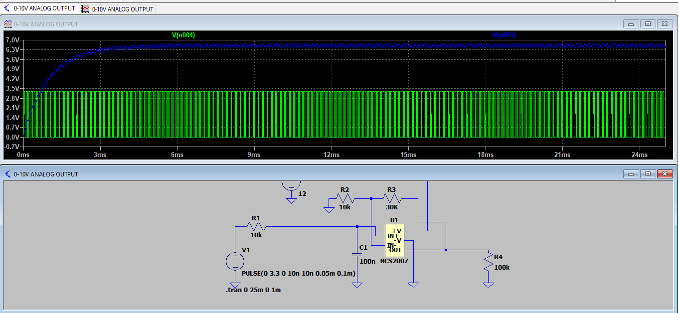
The timer configurated as a PWM generator of the STM32L073RZTx gives 3.3 V at 100% so I used a voltage follower with gain of 4 and an RC filter with a cut-off frequency of 160 Hz.

enter image description here

The op-amp I am using is the NCS20074DR2G Datasheet. It has a maximum output current of +-100 mA and it is capable of sourcing 60 mA when it is supplied with 10 VDC.

My questions :

  • Is this valve even controllable by a PWM signal?
  • What is the max. frequency of the PWM signal I can use ?
  • What is most crucial factor for the valve ripple voltage or response time of the filter? (for lower cut-off frequency I get less ripple on the other hand the response time increases to about 100 ms.)

enter image description here

enter image description here

\$\endgroup\$
3
  • 1
    \$\begingroup\$ I don't get why would you use a PWM if you already have a DAC output on STM32. Further, you only control the valve with this signal, the solenoid is driven from valve's electronics, not from you. \$\endgroup\$ Commented Dec 22, 2020 at 14:01
  • \$\begingroup\$ @MarkoBuršič I want to design 8 (0-10V) outputs. \$\endgroup\$
    – PCB-ABBS
    Commented Dec 22, 2020 at 14:09
  • 1
    \$\begingroup\$ OK. What a PWM has to do, then? And why are you asking about the PWM frequency that a valve should accept? \$\endgroup\$ Commented Dec 22, 2020 at 14:13

1 Answer 1

2
\$\begingroup\$

Is this valve even controllable by PWM signal?

Not directly; the ME4240 takes a PWM signal, but the ME4340 takes a voltage of 0 to 10 V (or 2 to 10 V) as the input signal. You can create that voltage from 3.3 V PWM with a low-pass filter followed by an amplifier with a gain of about 3 (or amplify first, then filter), and I assume that is what you are trying to do.

What is the max frequency of the PWM signal I can use ?

If you low-pass filter the PWM to get an adjustable voltage, then the higher, the better; it makes filtering easier. Go for the highest PWM frequency you can make with the STM32 that still gives you enough resolution.

What is most crucial factor for the valve, ripple voltage or response time of the filter?

It would depends on how fast you want the valve to react (and I don't expect them to be lightning-quick), but the higher the frequency of your PWM is, the higher the cut-off frequency of your low-pass filter can be, making it faster without much ripple. I have no idea what amount of ripple that valve actuator can endure, but I doubt it will be a problem if you set things up right. Also, nothing is stopping you from making a steeper filter should you need it, but I doubt you will.

\$\endgroup\$
3
  • 1
    \$\begingroup\$ Interesting point: "what amount of ripple that valve actuator can endure", why is this a factor? Voltage swing? Mechanical oscillations? I assume you mean ripple in the step response, or is it residual PWM ripple?. \$\endgroup\$
    – P2000
    Commented Dec 22, 2020 at 19:38
  • 1
    \$\begingroup\$ Ripple on the valve actuators input signal voltage. No idea what's inside these valve actuators, and how they react to ripple (size/frequency). It isn't specced, but I doubt very much it will be a problem (unless the ripple is very large and low-frequency enough to move the valve constantly, or make the input voltage go too far over the specced 10V sometimes). \$\endgroup\$
    – ocrdu
    Commented Dec 22, 2020 at 19:48
  • 1
    \$\begingroup\$ Ok, got it. Thanks! \$\endgroup\$
    – P2000
    Commented Dec 22, 2020 at 19:49

Your Answer

By clicking “Post Your Answer”, you agree to our terms of service and acknowledge you have read our privacy policy.

Not the answer you're looking for? Browse other questions tagged or ask your own question.