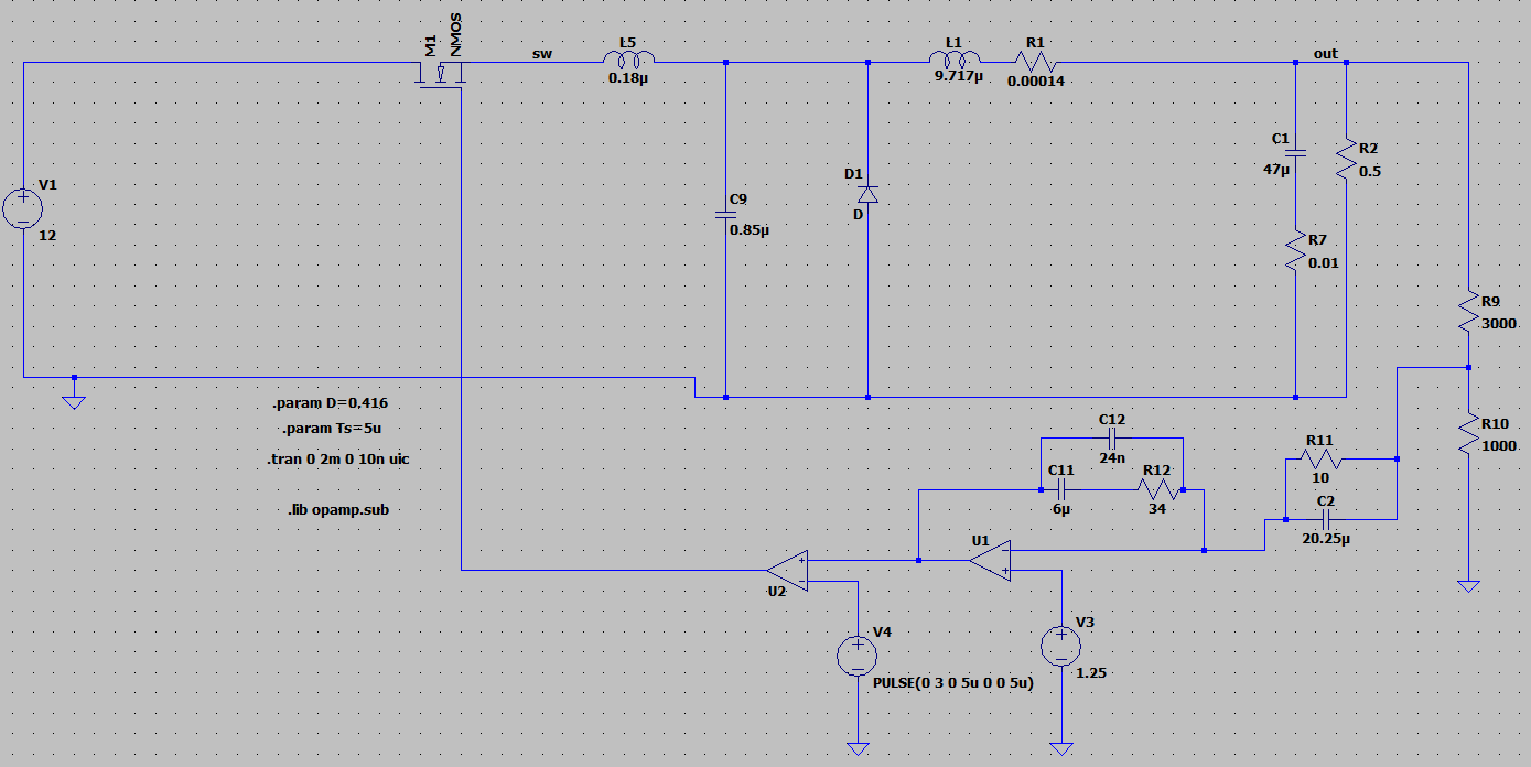
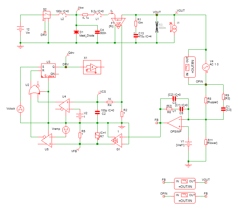
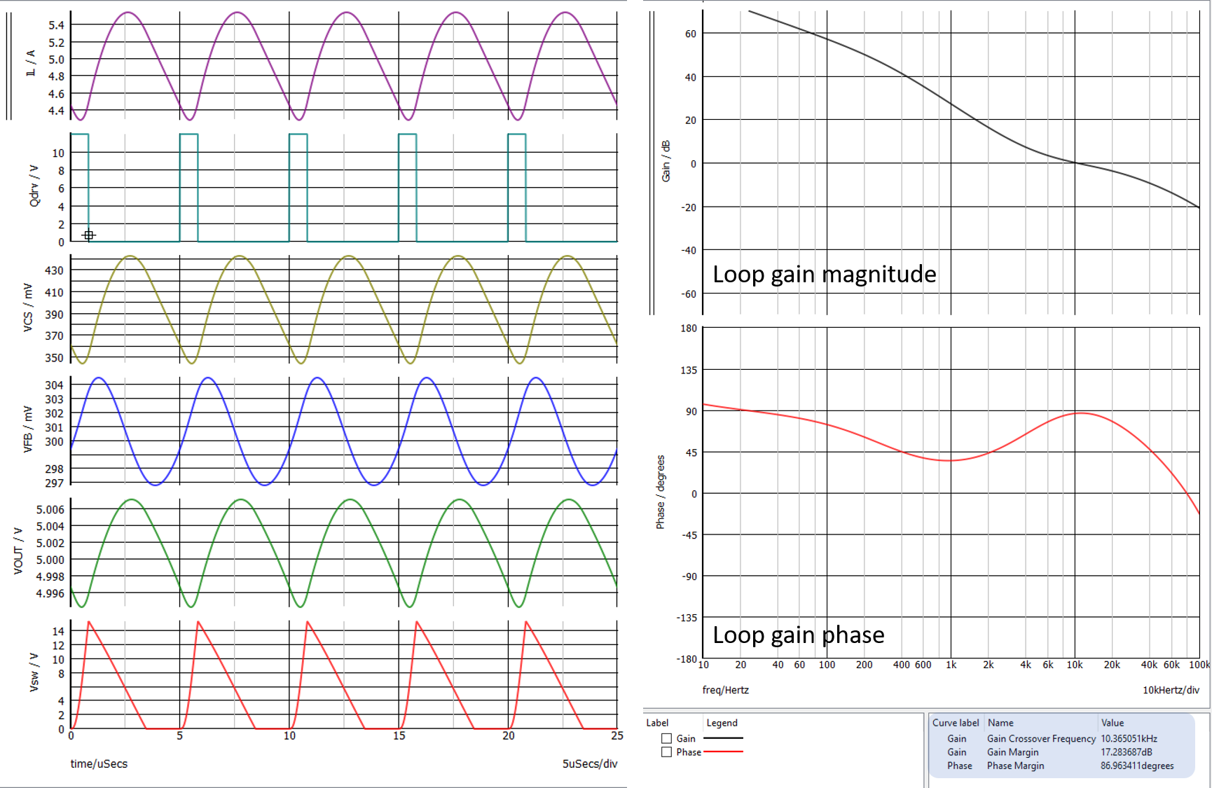
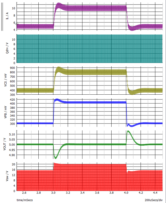
I designed a closed loop resonant buck converter using voltage mode control and simulated on PSIM. Here is my circuit:-
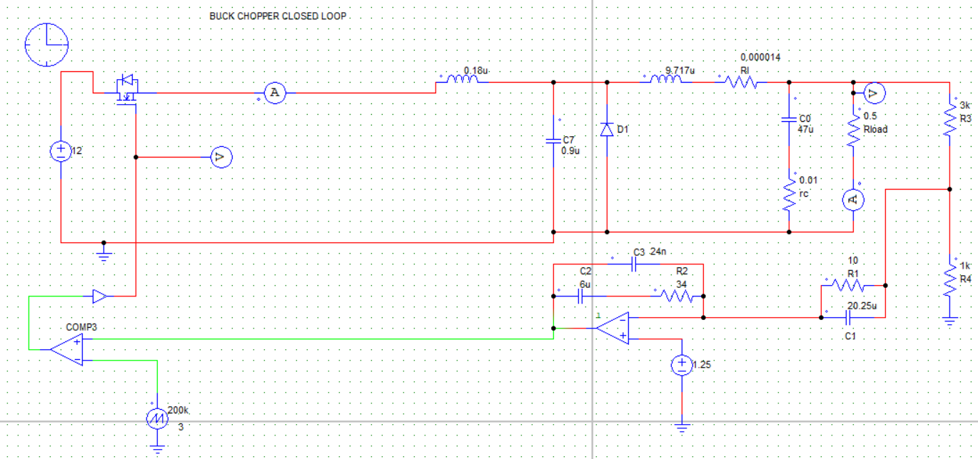
This gave correct results. Now I want to design an input filter so I simulated on LTSpice. In this circuit I had initially put a pulse voltage source at the Gate of the IRF530 and it was alright. Now I made the same circuit as in PSIM for the voltage feedback, but it is giving very wrong output waveforms.
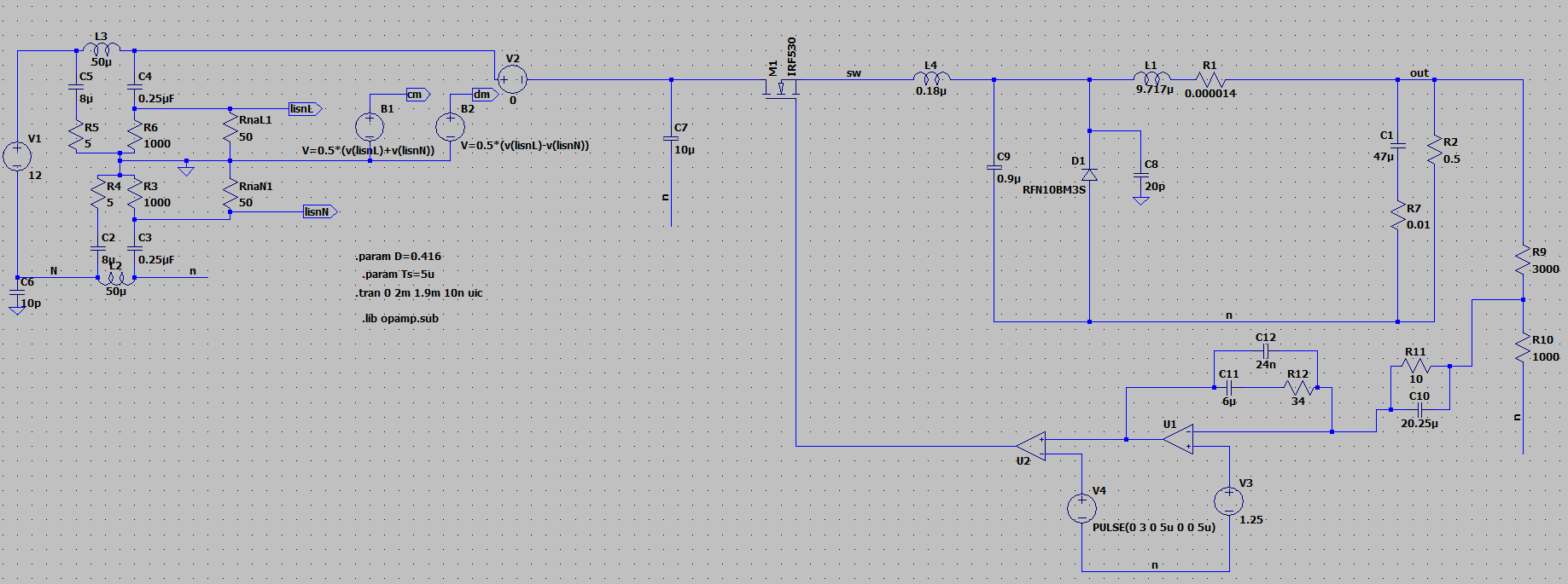
Here since I used LISN modules I did not ground the converter circuit instead it is all connected to the "n" label which is the eut point of a LISN box. C7 without this feedback was 4.7uF, but here in this circuit I changed it widely but the waveforms were all wrong. I will replace C7 by a damped filter. But first of all I need it to work as per the PSIM circuit before designing filter.
I know the problem lies in the feedback part because when I remove the feedback and put a pulse source, keeping the rest intact including the resonant components, I get perfect ZCS.
Also, if in the circuit in Ltspice (the image of which is attached) I remove the LISN blocks to make it absolutely same as in PSIM circuit, I still get erroneous waveforms.
EDIT 1:-
Here is the circuit without the LISN module, exactly the same as PSIM. Here I replaced the diode and MOSFET as ideal devices, but still not working.
