0
\$\begingroup\$

I'm trying to build simple 50Hz current transformer (just to see the mains current - maybe some microcontroller measurment in the future) following the answer to this question.

When I connect it to a 100W 240V light bulb (incandescent) the output sine wave is perfect.

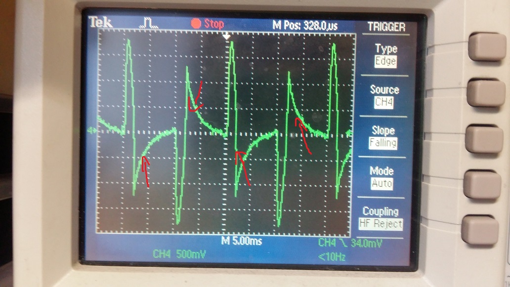
When I connect an SMPS (laptop charger) I get this strange waveform:

enter image description here

What is mostly strange for me is indicated with arrows. Why is that? Shouldn't be this flat after a peak?

enter image description here

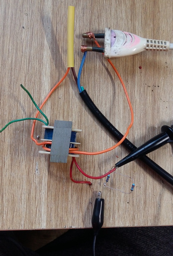
This is a photo of my setup:

enter image description here

This transformer is just small one (8W?) took from plugpack charger of some kind - 12V output. I'm measuring the waveform on its original primary side, loaded with 9kOhm resistor (two 18k in parrallel.)

Why is this waveform so strange? Is this transformer constuction ok? Maybe the inductances are too high/low?

EDIT

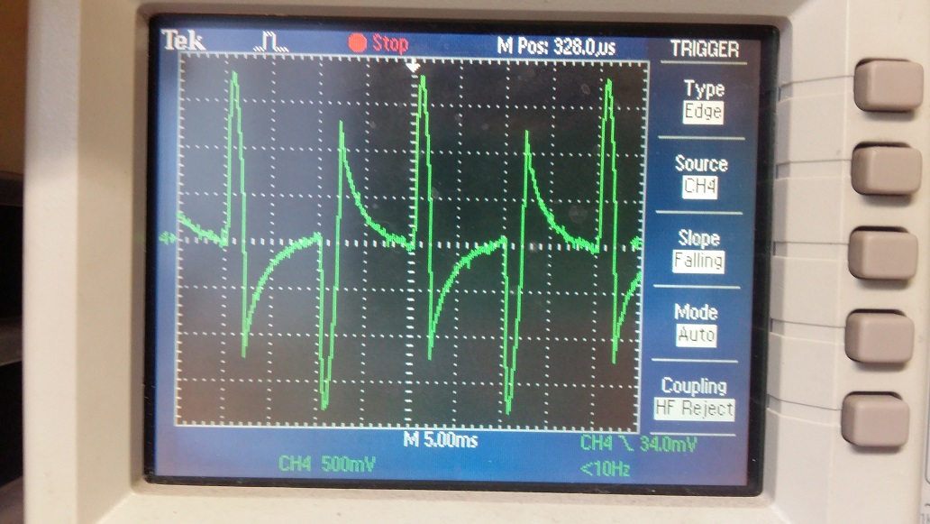
As Andy Aka suggested - I reduced the loading resistor value to 10Ohm. The waveform is now flat between peaks (as it should be), but the overall amplitude is very low - 20mV for 100W incandescent ligth bulb. Can I somehow increase the amplitude, or just add an amplifier?

What I tried to increase amplitude: I wound another 10 turns with thinner wire and connected this loading resistor there, now completly no voltage appeared on it, but according to the transformer formula, it should be quite large. Iout = Iin*(1/Nsec). For original primary N was like 2000 or so. Why then there is no voltage across this resistor?

\$\endgroup\$
6
  • 3
    \$\begingroup\$ Off topic, but you should really take more care building test setups like that. Get a proper female mains connector for one thing, to ensure proper and safe connections. Stuff like this is gonne bite you one day, literally and figuratively. \$\endgroup\$ Commented Jan 1, 2021 at 9:42
  • 1
    \$\begingroup\$ Poor PF of the power supply in combination with saturation of your current transformer? What’s your burden resistance an how many turns on the secondary? Can you estimate the cross section of your core? Try lowering the resistance and see if that helps. \$\endgroup\$
    – winny
    Commented Jan 1, 2021 at 10:38
  • \$\begingroup\$ @winny poor PF certainly but I doubt that a laptop SMPS will draw more power than a 100W bulb. The OP doesn’t say whether the SMPS is under load or not (the latter would be more forgivable). \$\endgroup\$
    – Frog
    Commented Jan 1, 2021 at 10:48
  • 1
    \$\begingroup\$ One is a resistive load, the other is not. The arrowed parts (exponential decay) suggest poor LF response in the measurement circuit : they should indeed be flat (and indicate zero current, not reversed wrt the conduction peak.). I am sure you can find a plausible explanation for the LF response. \$\endgroup\$
    – user16324
    Commented Jan 1, 2021 at 12:45
  • \$\begingroup\$ The burden resistor value times turns ratio times (average) current sets your required core size for a given frequency. If you unwind it, it looks like you have room for more primary turns. \$\endgroup\$
    – winny
    Commented Jan 1, 2021 at 23:29

2 Answers 2

4
\$\begingroup\$

I'm measuring waveform on It's original primary side, loaded with 9kOhm resistor (two 18k in parrallel).

Here's one big problem; you need to use much, much smaller values for the load resistor - it's called a burden resistor (when attached to a CT) and it MUST be low for a CT to work correctly. Try something like 10 Ω and re-measure the voltage waveform produced.

It's called a current transformer for a very good reason; current in produces current out and ideally, the output works best into a short but low value resistors are tolerated but, the core will saturate easily if the resistor is too high in value for a given input current.

Note also that the current waveform taken by a typical SMPS is going to be quite messy with lots of high frequencies and, unless you know the SMPS to be power factor corrected, you can't rely on it taking a stable sinewave-ish current.

When I connect it with 100W 240V light bulb (incandescent) - the output sine wave is perfect.

Well, you possibly got lucky in that the core didn't badly saturate without a low enough value of burden resistor.

\$\endgroup\$
1
\$\begingroup\$

Since the waveform is sinusoidal with a resistive load I’d be inclined to believe that this is the waveform for the SMPS and not an artefact of the CT. It looks like the SMPS is drawing more current early in the AC cycle when the voltage is low, and reducing the current as the voltage increases. I’m guessing that the largest peaks occur just before the AC crosses zero. Well designed equipment should have a more or less sinusoidal current profile, but lots of devices, especially lower-power ones don’t.

\$\endgroup\$
4
  • \$\begingroup\$ Having just read Andy Aka’s answer I agree that the burden resistor is much too large and the SMPS will be struggling to operate at all, since the CT will be dropping a lot of voltage. \$\endgroup\$
    – Frog
    Commented Jan 1, 2021 at 10:52
  • \$\begingroup\$ "Since the waveform is sinusoidal" -- it's not a good assumption. That's the current into a bridge + cap, which is far from sinusoidal. \$\endgroup\$ Commented Jan 1, 2021 at 16:03
  • \$\begingroup\$ ... with a resistive load, as the OP stated \$\endgroup\$
    – Frog
    Commented Jan 2, 2021 at 3:35
  • \$\begingroup\$ If the input current is distorted, the output will not be sinusoidal if a resistive load is attached. The other answer got it right: quick example. \$\endgroup\$ Commented Jan 2, 2021 at 16:37

Your Answer

By clicking “Post Your Answer”, you agree to our terms of service and acknowledge you have read our privacy policy.

Not the answer you're looking for? Browse other questions tagged or ask your own question.