I've read many times some statements about resonators like this (reference):
Resonant circuits are circuits, which offers a high impedance or low impedance (for parallel and series resonance respectively) to the source at a particular frequency of operation. The frequency at which the resonant circuit has a very high or low impedance is called its resonant frequency.The frequency selectivity property of resonant circuits are exploited in building filter circuits
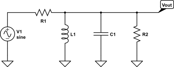
1) It's a basic concept that is written everywhere, but I cannot understand in practice how resonators may filter an input signal. Precisely, let's consider a parallel RLC circuit:
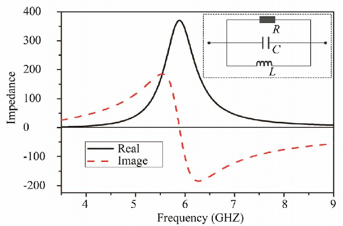
It may represents different kinds of resonators. It's simple to find that the input impedance of the parallel RLC circuit which represents the resonator is the following one (in terms of real and imaginary parts):
If we look at the graph, I understand the initial statement: this graph is very frequency - selective.
But let's look at the RLC circuit: what does it filter? There is an input voltage signal. If I take the voltage across one of RLC components, it will be the same of the source. I'd say that this circuit, given an input voltage signal, gives an output filtered current. So, how should I read this filtered current (from a circuital point of view).
2) What If the parallel RLC circuit is only a model (not a real circuit) of a cavity/waveguide resonator (i.e. a closed tube of metal in which there is my electromagnetic source)? My electromagnetic source (consider a simple antenna) generates an EM field with some frequencies, and the cavity selects only specific frequency. How may I read the filtered signal?


