0
\$\begingroup\$

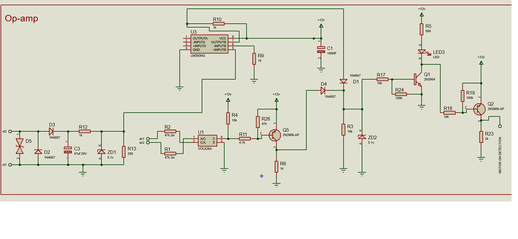
I am using this circuit to detect whether or not electricity is being consumed.

There are two sensor sources (CT1 & CT2 ) where a CT coil will be installed. When electricity passes through that wire then a CT coil produces a corresponding voltage which is given to comparator IC (LM393).

The LM393 compares the input and a logical output is feed to D1. Similarly if electricity passes through AC1 & AC2 then a corresponding logical voltage is generated through Q5 and fed to D4. Using D1 & D4 an OR gate output is generated & passes through the Zener diode. The Zener is used to get lower voltage to the transistor circuit. After that the Zener output is given to Q1 to get LED status and Q2 to get logical output.

Please guide wherever correction is required in circuit so that it can run for a long time without get faulty.

enter image description here

\$\endgroup\$
10
  • \$\begingroup\$ Let's start with your overall specifications. You say you want to detect whether electricity is being "consumed". I am not sure what you mean by consumed? Do you mean that there is both 1) current flowing through a wire, and 2) a voltage between two different circuit points. However, you don't need to multiply them to get the power, but simple detect that both are present. Is that correct? If so, what are the threshold values for voltage and current that signify that voltage is present and that current is present? \$\endgroup\$ Commented Jan 7, 2021 at 3:39
  • \$\begingroup\$ Yes i want to simply detect whether electricity is available or not. For this i am using two sensor module. One is ct sensor & another is optocoupler. I have to use both sensor. If electricity is detected through any one of them a logical output should be generated. There is no threshold value for voltage and current. Simply either electricity is not available i.e. 0v or no current flowing. Or electricity is available i.e. 220v or current flowing. Sorry for the bad english. \$\endgroup\$
    – manish
    Commented Jan 7, 2021 at 3:58
  • \$\begingroup\$ Electricity may be available whenever there is a voltage from a source with sufficiently low impedance. That doesn't mean that the electricity is power is being consumed? Electricity is available at a wall outlet, and you can detect that it is available by testing the voltage at the outlet. but no power is being used if nothing is plugged in. So do you want to detect that electricity is available? Or that it is being used? \$\endgroup\$ Commented Jan 7, 2021 at 4:05
  • \$\begingroup\$ I want to just detect ... Not being used \$\endgroup\$
    – manish
    Commented Jan 7, 2021 at 4:10
  • \$\begingroup\$ Then what is the current transformer for? \$\endgroup\$ Commented Jan 7, 2021 at 4:27

1 Answer 1

0
\$\begingroup\$

Please guide wherever correction is required in circuit so that it can run for a long time without get faulty.

The LM393 comparator has its '-' input connected to ground through R9, and the '+' input will be at ground potential or higher, so (depending on the individual part's input offset voltage) it may cause the output to stay permanently high. Even if it doesn't stay high all the time, it will be very sensitive to noise. You should put a 'reference' voltage on the '-' input to set the current at which the comparator switches.

Without knowing the sensitivity of your current transformer and the motor's operating current I can't tell you what reference voltage is required. It might be be best to apply it through a potentiometer so the threshold can easily be adjusted. the current transformer's output is limited to ~5.1 V, so the reference voltage only needs to be adjustable between 0 and 5.1 V.

Next problem is there is no explicit limit on current flowing through Q5, D4 and ZD2. Over 200 mA could pass when the optocoupler is turned on, which would overheat Q5 and ZD1. This can be fixed by adding a resistor in series with D4. 1 kΩ should be enough.

The optocoupler's output is not continuous, but drops out at each zero crossing. The dropout time is short compared to the total mains cycle time, but might upset a detector that expects to see a solid logical output. To 'fill in' these short dropouts you could add a capacitor across R3. 1 μF should be enough to remove dropouts of up to ~7 ms.

I can't see any other obvious errors, but you might consider adding a resistor in series with the output to limit current in case of a short circuit.

\$\endgroup\$
7
  • \$\begingroup\$ thanks @bruce abbott sir please find the link of CT sensor specification of model no L01-6220.Please guide accordingly. drive.google.com/file/d/1rdE73qPkwk4g5AQUKVZn_QCx7Gr5Sduy/… Please also find the link for updated circuit diagram as you per your suggestion.Please check is it ok ? drive.google.com/file/d/1oWWWbGHchalQP-R4pxW4lZUAF3dsl6bl/… you might consider adding a resistor in series with the output to limit current in case of a short circuit" means should i add resistor in series at output point (motor on detection). \$\endgroup\$
    – manish
    Commented Jan 7, 2021 at 8:39
  • \$\begingroup\$ "should i add resistor in series at output point (motor on detection)." - yes. \$\endgroup\$ Commented Jan 7, 2021 at 9:34
  • \$\begingroup\$ @ bruce abbott Please check improved design as per your suggestion. is it correct now ? drive.google.com/file/d/1kP0-D_WPKIBN3yWj5HqVFcOi19CYkI2R/… \$\endgroup\$
    – manish
    Commented Jan 7, 2021 at 11:10
  • \$\begingroup\$ Yes, although the pot will be effective over less than half its range. I would put a resistor in series from +12V to the pot to reduce its range, eg. 560k would give an adjustment range of ~0-5.7V \$\endgroup\$ Commented Jan 7, 2021 at 19:46
  • \$\begingroup\$ thanks a lot for the guidance @bruce abbott \$\endgroup\$
    – manish
    Commented Jan 8, 2021 at 8:30

Your Answer

By clicking “Post Your Answer”, you agree to our terms of service and acknowledge you have read our privacy policy.

Not the answer you're looking for? Browse other questions tagged or ask your own question.